P/N 960-000180R_Rev. 1 {EDP #233427} © 2016, JAPAN CASH MACHINE CO., LTD.
DBV® Series
DBV-400 Banknote Validator
Section 2
This section provides installation and operating
instructions for the DBV
®
Series DBV-400
Banknote Validator Unit. The following informa-
tion is discussed within this section:
• Installation Procedure
• DIP Switch Configurations
• Connector Pin Assignments
• Preventive Maintenance
• Standard Interface Circuit Schematics
• Operational Flowchart
Installation Procedure
The DBV-400 Frame Unit provides installation
grooves (notches) for each surface.
Entire Unit Installation
Perform the following steps to install the DBV-400
Unit:
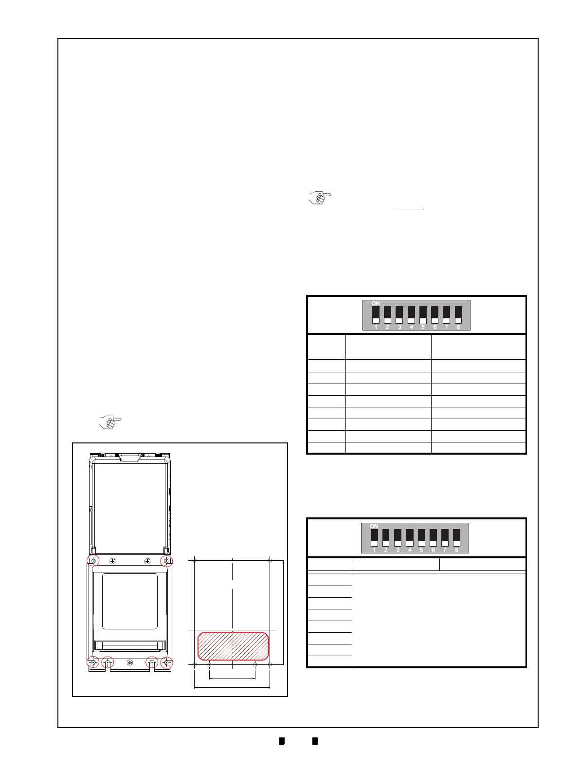
1. Place the DBV-400 Unit Frame cut outs (Figure
2-1 a
1
through a
4 and
b
1 &
b
2
) onto the threaded
studs on the chassis.
2. Secure the rear side of the DBV-400 Frame to the
chassis with six (6) nuts.
DIP Switch Configurations
This section provides the DIP Switch Block 1 (DIP
SW1
) and Block 2 (DIP SW2) Settings for the
DBV-400 Unit and its Bezel.
DIP Switch Block 1
DIP Switch Block 1 (DIP SW1) is used to Accept
(enable) or Inhibit (disable) acceptance of each
Banknote denomination.
DIP Switch Block 2
DIP Switch Block 2 (DIP SW2) is used to set
various functions.
NOTE: Refer to “Unit Dimensions” on
page 1-8 for each Bezel’s dimensions.
Figure 2-1 Threaded Studs Location
Figure 2-1 Threaded Studs Location
a
1
a
2
a
3
a
4
b
1
b
2
Chassis Side
Reference Dimensions
Insertion Slot
Area (Open)
Table 2-1 DIP Switch Block 1 Settings
Switch
No.
Switch ON Switch OFF
1
VEND 1 INHIBIT VEND 1 ACCEPT
2
VEND 2 INHIBIT VEND 2 ACCEPT
3
VEND 3 INHIBIT VEND 3 ACCEPT
4
VEND 4 INHIBIT VEND 4 ACCEPT
5
VEND 5 INHIBIT VEND 5 ACCEPT
6
VEND 6 INHIBIT VEND 6 ACCEPT
7
VEND 7 INHIBIT VEND 7 ACCEPT
8
TEST MODE FUNCTION
Table 2-2 DIP Switch Block 2 Settings
Switch No. Switch ON Switch OFF
1
Refer to the “Software Information Sheet” for
details on DIP Switch Block 2 (DIP SW2) settings.
2
3
4
5
6
7
8
NOTE: Turn the Power Supply to the DBV-
400 Unit OFF before
configuring settings on
DIP Switch Block 1 and Block 2.