P/N 960-000180R_Rev. 1 {EDP #233427} © 2016, JAPAN CASH MACHINE CO., LTD.
Section 6 DBV® Series DBV-400 Banknote Validator Calibration and Testing
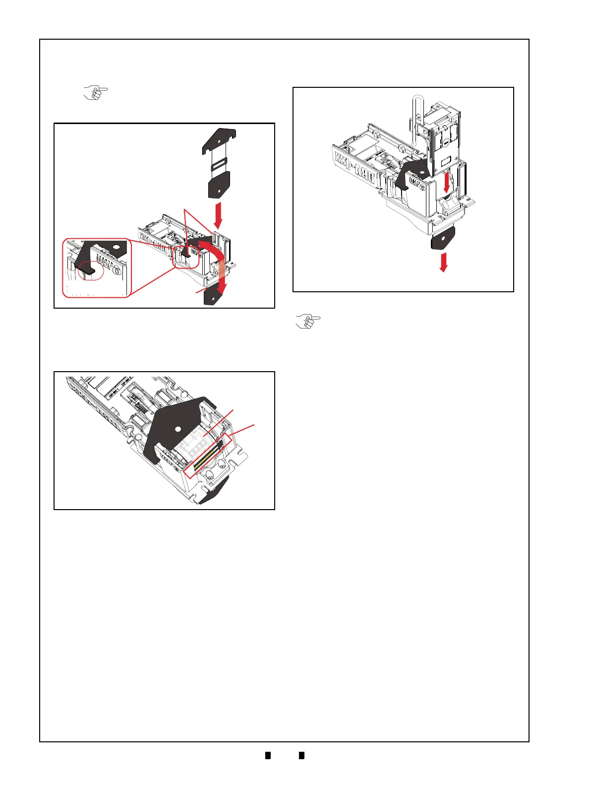
5. Hook the KS-095A Reference Paper Tabs into
both sides of the Cut-out Space on the DBV-400
Unit (Figure 6-27 c).
6. Place the KS-095A Reference Paper
(Figure 6-28 b) in the center of the Transport Path
to ensure the Inside Sensors are covered by the
Reference Paper as shown in Figure 6-28a.
7. Firmly set the Validation Guide (Figure 6-29 a)
while adjusting the KS-095A Reference Paper
(Figure 6-29 b) placement location until the
Guide “clicks” into place, and ensure that it is
tightly locked.
8. Pull the KS-095A Reference Paper (Figure 6-29
b) just slightly in the direction indicated by the
red arrow A until the Reference Paper is taut.
NOTE: Make sure that the Reference
Paper Tabs are firmly hooked into the
Cut-out Space.
Figure 6-27 Placing KS-095A Reference
Figure 6-27 Placing KS-095A Reference Paper 4
Figure 6-28 Placing KS-095A Reference Paper
Figure 6-28 Placing KS-095A Reference Paper 5
Figure 6-29 Placing KS-095A Reference
Figure 6-29 Placing KS-095A Reference Paper 6
NOTE: Make sure that the Guide Chip A
(Figure 6-26 a) and Guide Chip B (Figure
6-26 b) are set back in the DBV-400 Unit
after calibration is complete.