P/N 960-000180R_Rev. 1 {EDP #233427} © 2016, JAPAN CASH MACHINE CO., LTD.
Disassembly/Reassembly DBV® Series DBV-400 Banknote Validator Section 4
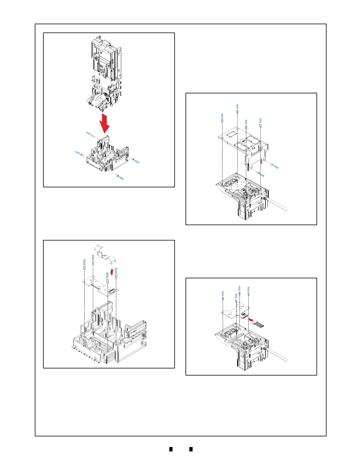
3. Unplug the single (1) Connector (Figure 4-11 a).
4. Remove the four (4) Mounting Screws (Figure 4-
11 c
1
through c
4
) securing the Inside Validation
Sensor Board (Figure 4-11 b), and remove the
Inside Validation Sensor Board from the Valida-
tion Guide Cover D4 (Figure 4-11 d).
Outside Validation Sensor Board
Removal
To remove the Outside Validation Sensor Board,
proceed as follows:
1. Remove the six (6) Mounting Screws (Figure 4-
12 b
1
through b
6
) securing the Outside Guide
Cover (Figure 4-12 a) to the Validation Guide
(Figure 4-12 c).
2. Unplug the single (1) Connector (Figure 4-13 a).
3. Remove the four (4) Mounting Screws
(Figure 4-13 b
1
and b
4
) securing the Outside
Sensor Board (Figure 4-13 c), and remove the
Outside Validation Sensor Board from the Valida-
tion Guide (Figure 4-13 d).
Figure 4-10 Validation Guide Removal
Figure 4-10 Validation Guide Removal
Figure 4-11 Inside Validation Sensor Board
Removal
Figure 4-11 Inside Validation Sensor Board
Removal
Figure 4-12 Outside Guide Cover Removal
Figure 4-12 Outside Guide Cover Removal
Figure 4-13 Outside Validation Sensor Board
Removal
Figure 4-13 Outside Validation Sensor Board
Removal