110
8. Channel 2 2nd harmonic.
9. Channel 2 3rd harmonic.
10. Channel 2 4th harmonic.
11. Channel 2 1st harmonic wave phase
Description: Test of transimpedance and unbalance signal ampli! ers. This test will take 12 seconds.
Special function: All values displayed in channel 1 are related to the rear transducers and those in channel 2 are
related to the front one.
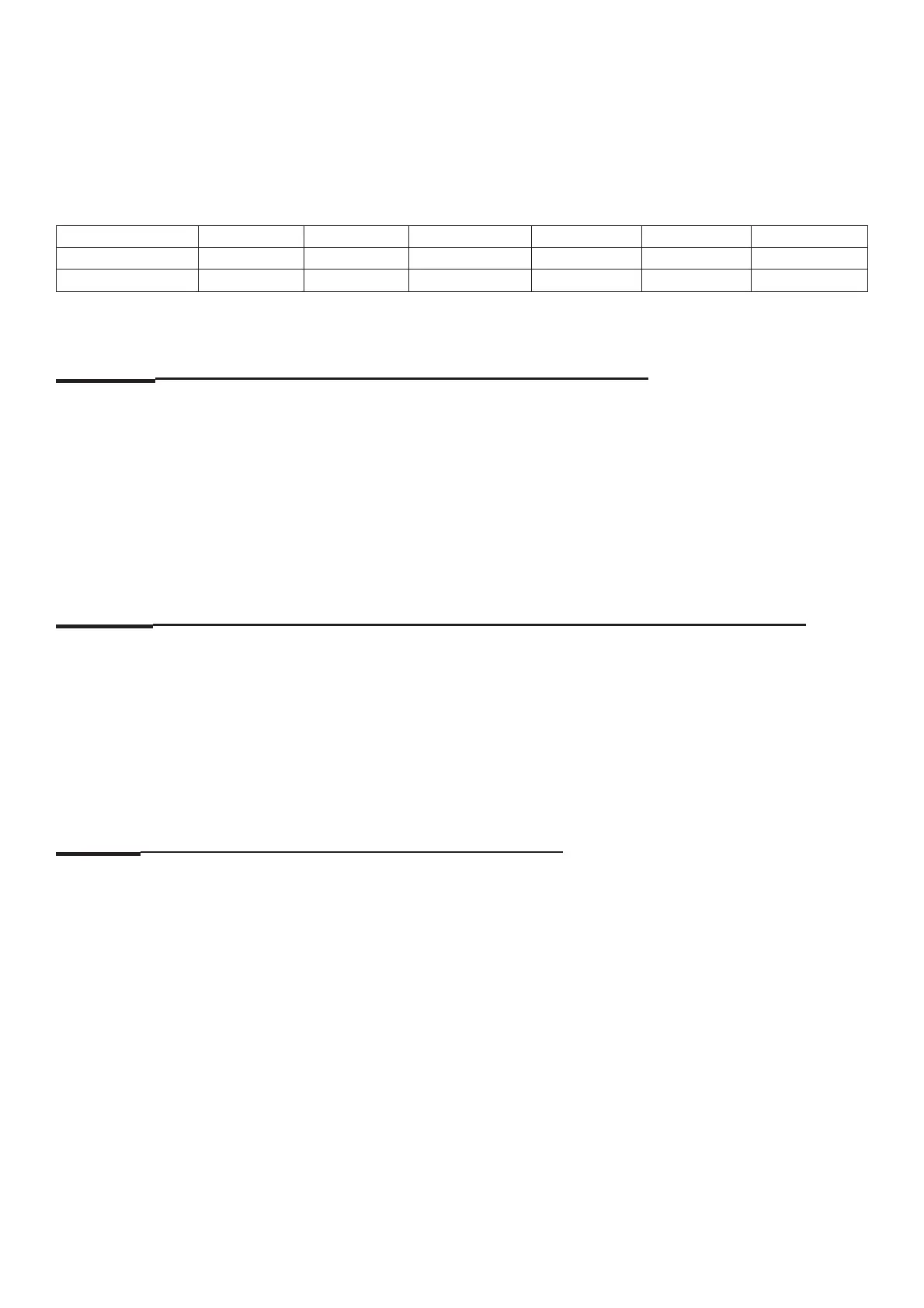
Offset 1
ST
2
ND
3
rd
4
th
Phase
CHANNEL 1 0.00-0.10 0.10-0.25 0.00-0.02 0.03-0.08 0.00-0.01 -10°/+10°
CHANNEL 2 0.00-0.10 0.10-0.25 0.00-0.02 0.03-0.08 0.00-0.01 -10°/+10°
C104 Test the RC time constant of the unbalance transducers
Options: None
Special function: None
Description: Indication of the unbalance transducer RC time constants.
A “1” in the left and the right display will be indicated, if both transducers are OK.
Otherwise an error code will be displayed.
Comments: None
C110 Indication of the operating voltages supplied by the power supply module
Options: None.
Special function: None.
Description: Indication of the operating voltage, 5.0 VDC, supplied by the power supply module for the controller
board
Comments: Please refer to error ID 810 and 811 for the limits.
C111 Belt tension: Measure fi rst harmonic of the belt
Options: FOR STEEL VPM ONLY
Special function: None.
Description: None.
Comments: Only for belt driven balancer.