34
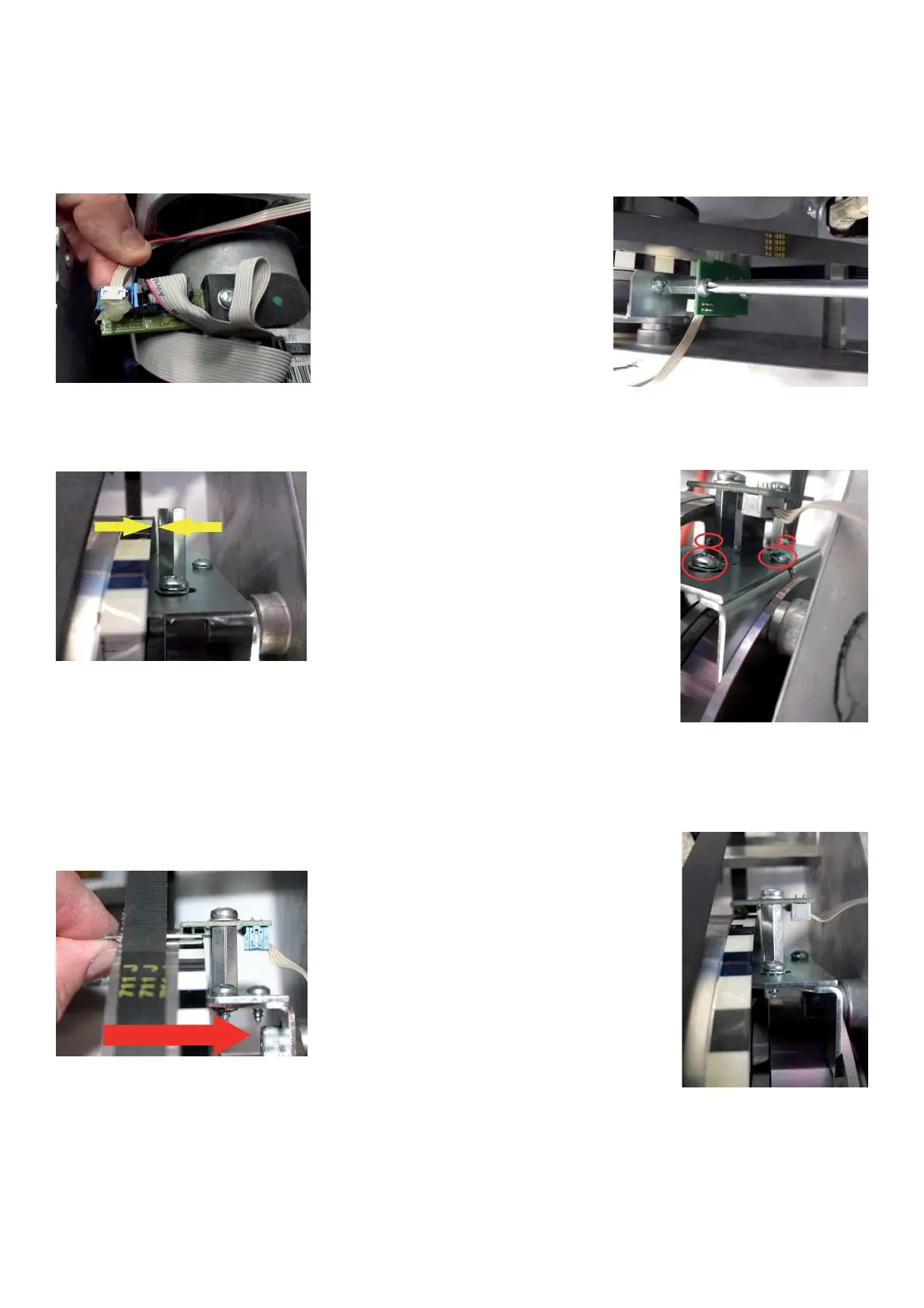
TO REPLACE OF THE POWER CLAMP ENCODER BOARD.
Ø Disconnect power supply.
Ø Remove weight tray.
Ø Disconnect the 4 Pin ribbon cable from the optoencoder PCB.
Ø Remove the phillip screws holding the encoder board to the bracket.
Ø Turn the pulley sheave by hand making sure that it turns freely and does not rub against the encoder standoffs.
If the pulley rubs against the standoffs, loosen the four screws securing the bracket and using the spacer gauge
adjust the bracket so that the spacers are at 1,5mm (.063) from the pulley.
Ø Install the new encoder board. The correct gap from the pulley must be from 0,5mm to 0,6mm ( 0.02” to 0.023”).
Ø Make sure that it reads the small and wider strip zones.
Ø To adjust the gap unlock the screw shown by the arrow and then lock it ! rmly again.
Ø After the blocking of the screw check again the gap.