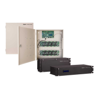
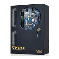
iSTAR Edge G2 Controller Installation and Configuration Guide 19
Chapter 2 - Installation Prerequisites
Wiring Distances
The iSTAR Edge G2 supplies 12V at its reader connectors. To determine the maximum wiring distance of a reader from an
iSTAR Edge G2, check the voltage that reaches each reader and compare the voltage with the minimum requirements in the
Minimum Reader Voltage table.
NOTE
USB connections must be wired within 25ft of the iSTAR Edge G2 to maintain UL compliance.
Table 7:Minimum Reader Voltage
Reader Minimum Voltage
RM Series Reader or RM-4 board 7.5 V
RM-4E 11 V
If the voltage does not meet the minimum requirements for the reader, shorten the wire length, use a heavier gauge wire, or add
a UL294-listed power-limited power supply. Refer to the wire resistance table to assist in choosing a different gauge of wire.
Table 8:Wire Resistance
Wire Gauge (AWG) Resistance per 1000ft
24 26 Ohm
22 16.5 Ohm
20 10.2 Ohm
18 6.5 Ohm
NOTE
Number of devices on the bus, current draw of each device, wiring length between devices and controller, wire gauge, power supply
tolerances, and battery state (for aPS) can impact on the actual voltage reaching the reader.
Host System Requirements
The iSTAR Edge G2 requires a host computer configured as a C•CURE server/host. For more information on hardware and
software requirements for C•CURE, see the
C•CURE 9000 Installation and Upgrade Guide
.
Grounding Requirements
Ensure the iSTAR Edge G2 controller is connected to an earth ground at the ground stud in the cabinet using 16 AWG, or
larger, wire. Ensure that the shield wires are also grounded to the nearest earth/ground connection at one end of the cable.
NOTE
When servicing, disconnect the ground wire last in order to provide maximum protection to the equipment and personnel from electrical
current.

 Loading...


