iSTAR Edge G2 Controller Installation and Configuration Guide 47
Chapter 6 - Connections
Inputs
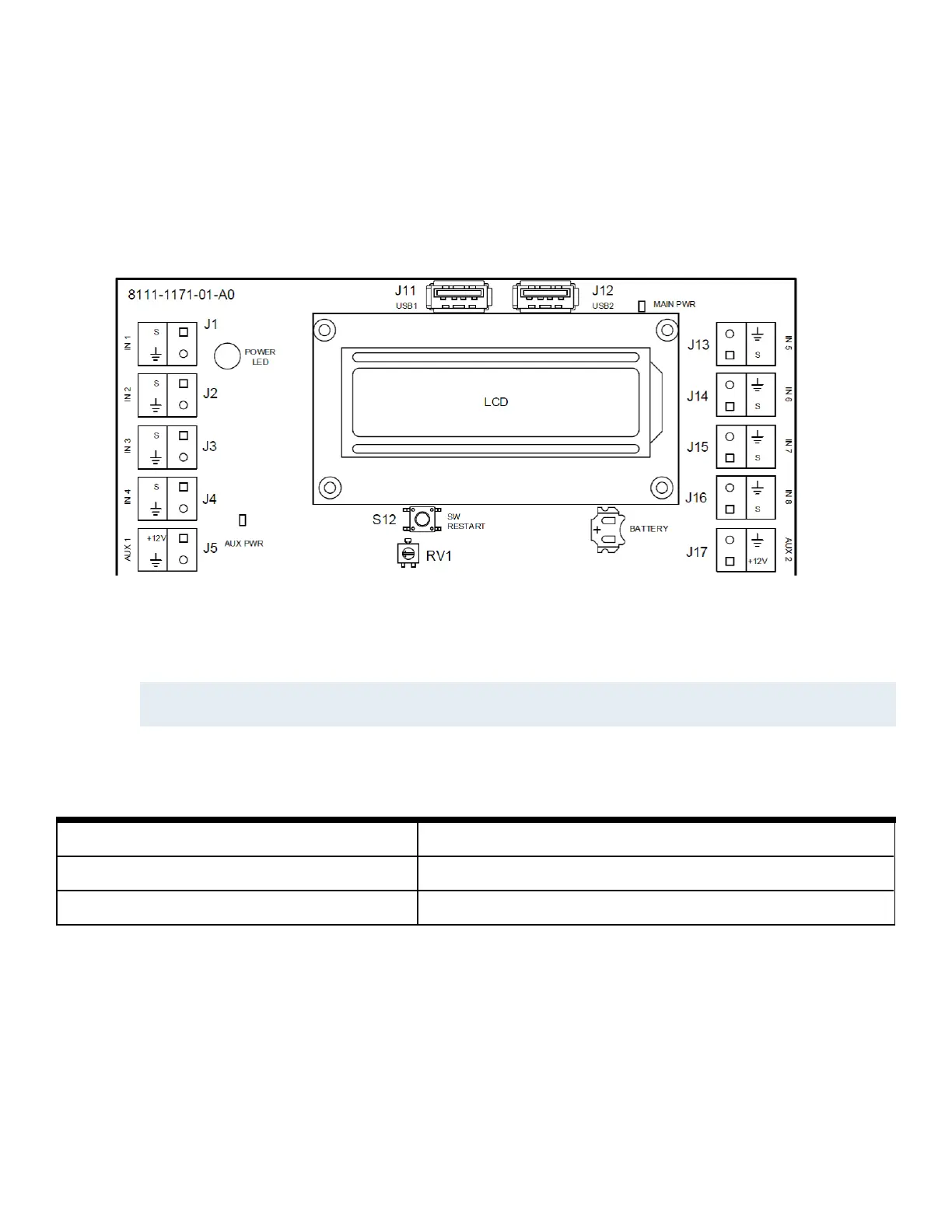
There are 8 onboard inputs on the iSTAR Edge G2, shown in Figure 10. Pin 2 of the Input connectors is Ground.
Figure 10:Onboard Inputs
The supervision mode is configured in the host. Supervision modes are listed in Table 18 on Page 48.
Values for resistor configurations are described in terms of NC (Normally Closed) or NO (Normally Open), resistor placement,
and supervising resistor value.
NOTE
For UL listed products, burglar alarms must be supervised.
Resistor placement refers to how many EOL (End Of Line) resistors are used and where they are placed in relation to the
switch. Settings are described in Table 17.
Table 17:Resistor Settings
Non-Supervised The user wires no external resistors.
Single EOL The user wires a single EOL resistor.
Double EOL The user wires 2 EOL resistors, 1 in parallel, and 1 in series with the switch.
Resistor values are labeled as 1k/5k/10k (in Ohms). In the Double EOL cases, both resistors have the same value.
 Loading...