iSTAR Edge G2 Controller Installation and Configuration Guide 54
Chapter 6 - Connections
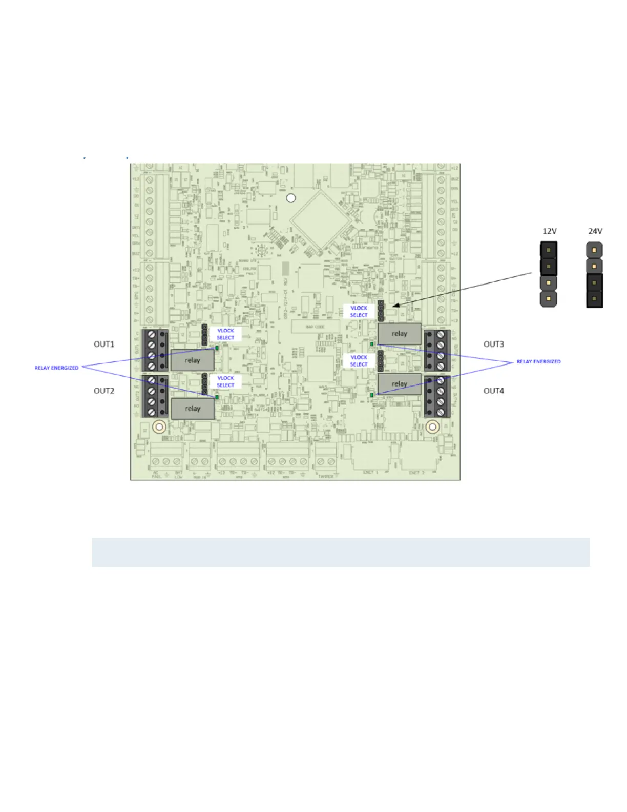
Relay Outputs
iSTAR Edge G2 relays can be used as DRY or WET. There is a jumper for each relay to set the mode.
Figure 17:Relay locations
Each Relay has an LED to show whether the relay is being energized or not. Each relay has a 4-pin header to configure
whether 12V, 24V or no power is being supplied to the output.
NOTE
To avoid placing a large current burden on the 24V-to-12V convertor on the board, avoid configuring the relay outputs for 12V if 24V
power is supplied to the board.
Placing the shunt on the middle two pins configures the output as DRY(i.e. no power supplied), as shown in Figure 17.
Dry Relay Wiring
Figure 18 shows DRY relay wiring. Max current is 3A at 30 VAC/VDC. Use NO or NC as appropriate. Notice that jumper is in
the DRY position.
 Loading...