iSTAR Edge G2 Controller Installation and Configuration Guide 36
Chapter 5 - Controls and Displays
Visual Indicators
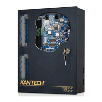
iSTAR Edge G2 contains a number of visual indicators.
NOTE
The iSTAR Edge G2 LCD display and associated diagnostic tests have not been evaluated by UL.
LCD
The LCD display displays status messages and diagnostic information, not access control information.
• Diagnostics are controlled by the rotary switch, SW1.
• LCD display contrast is controlled by the potentiometer, RV1.
• Backlight is on when door is open, off when door is closed, and during power-fail backups.
Common displays are:
• iSTAR boot information
• Firmware version
• Controller status information
• Master Connected or Host Connected
• IP address of Host or Master
• Name of iSTAR Edge G2 and MAC address
• IP address of iSTAR Edge G2
• Member or Master with date and time
• Configured Power and Measured Power
• Cluster Connected or Split
• Indication of whether a DB is restored.
• Diagnostic results
LEDs
The super-bright white Power LED is illuminated when the enclosure door is closed, i.e. when the tamper switch closes. The
power LED has varying brightness from 12V to 24V and extinguishes at ~8V.
NOTE
The relay activation LEDs remain active regardless of the state of the enclosure door.
The remainder of the indicators are illuminated when the enclosure door is opened. The LCD backlight and all LEDs other than
the power LED and the relay LEDs are under firmware control and are extinguished when the unit detects input power failure
and enters sleep mode to minimize power consumption. Table 13 on Page 37 displays the operation of the LEDs.
 Loading...