8.4 REPLACEMENT OF MAJOR PARTS
ņ36
8
yyyy
yyyy
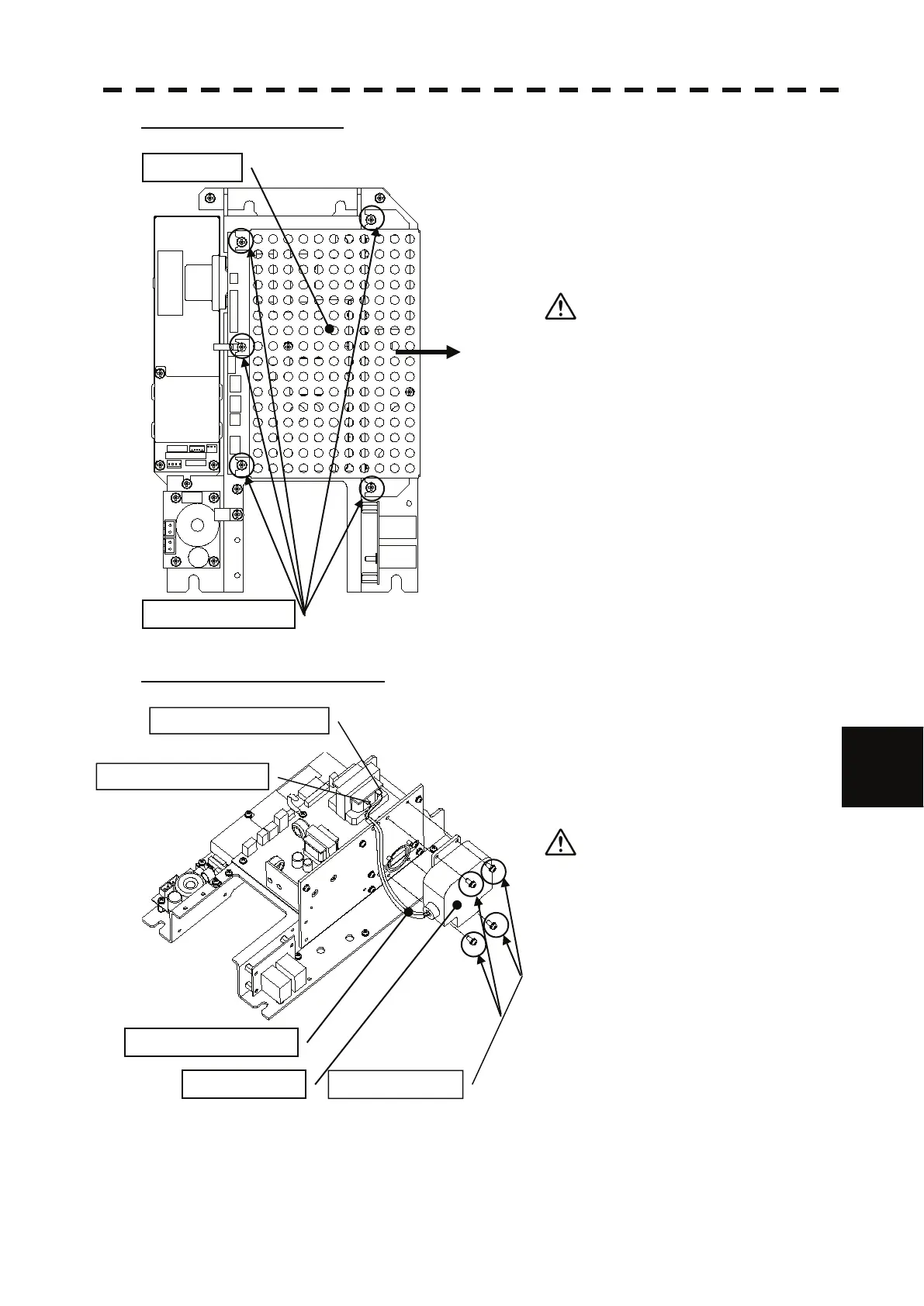
Step 5: Remove the cover.
Loosen all the screws (5 places).
Slide the cover to the right and remove it.
Use a shielded screw driver.
Metal (tools) may deteriorate if they
come in contact with the magnetron.
Remove the screws (4 places).
Remove the magnetron cable (solder).
Replace the magnetron.
Step 6: Replace the magnetron.
Two silicon tubes are moved to the magnetron
cable for the exchange and it changes it.
Replace the magnetron.
Please solder with a correct terminal
when you solder a yellow terminal and
a green terminal with the pulse
transformer. Moreover, please note that
solder might not fall on the circuit when
soldering.
Reverse the order to complete the procedure.
Make sure that all bolts and screws are
tightened again, and all cables are properly
re-connected.
This completes the magnetron replacement
procedure.
Cover
Screws (5 places)
Magnetron
Silicon tubes (2 pieces)
Screws (4 places)
Green terminal (solder)
Yellow terminal (solder)
 Loading...


