8.4 REPLACEMENT OF MAJOR PARTS
ņ38
8
yyyy
yyyy
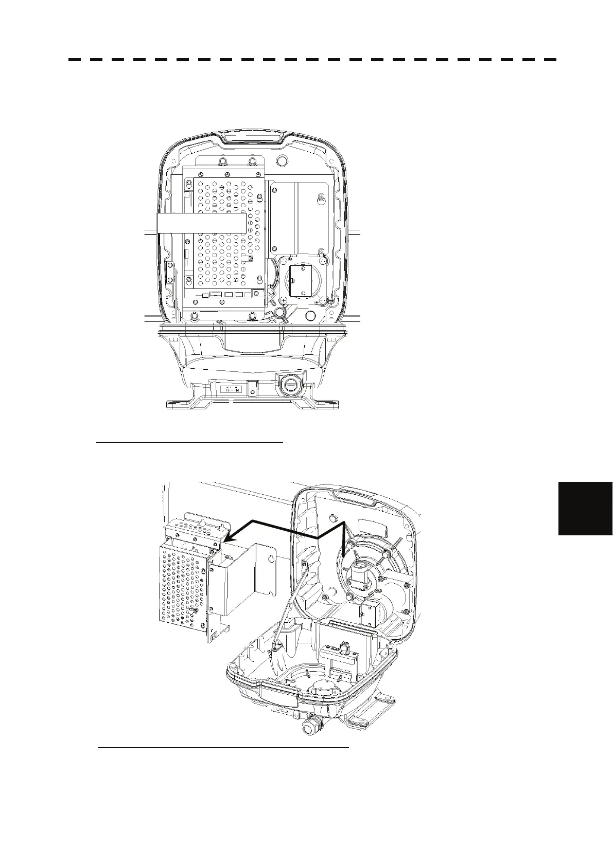
The transceiver unit is fixed with 4 upset head bolts with washer (M5X16SUS_SW_W)
and 2 upset head bolts with washer (M4X10SUS_SW_W).
Loosen those bolts.
Step 3: Remove the transceiver unit.
Remove the transceiver unit.
When removing the transceiver unit, once slide it to upper direction and pull it off.
Perform the replacement of circuits within the transceiver unit in a safe place.
Step 4: Remove the cover of the transceiver unit.
Perform the replacement of circuits and parts within the transceiver unit.
Remove the cover of the transceiver unit.
The cover is fixed with 4 built-in M4X10Bs_SW_LW screws.
Transceiver Unit
 Loading...


