EasyManuals Logo

JRC JMA-5312-6 User Manual

JRC JMA-5312-6
492 pages
To Next Page IconTo Next Page
To Previous Page IconTo Previous Page
Page #468 background imageLoading...
Page #468 background image
Filter
PWR
SENSE
P12V
±12V
AVR
DC24V
PWR
CONT
Relay
+5V AVR
+3.3V AVR
Poly-SW
Poly-SW
Filter
Filter
Motor
Control
AVR
internal circuit
power
-12V 0.2A
+12V 1.0A
Analog
Analog
Logic
Logic
4A
7A
Motor
PWR-ON
0.5A
0.5A
SCANNER UNIT NKE-1130
RADAR PROCESS UNIT NDC-1417
LCD MONITOR
NWZ-173
F3
POWER-SW
OPERATION UNIT NCE-5171
To GPS (SW)
4A
JUNCTION BOX
NQE-3151A
AC100-120/220-240V,
50/60Hz, 1
RECTIFIER UNIT
NBA-5111
AC100-115V, 50/60Hz, 1
AC220-240V, 50/60Hz, 1
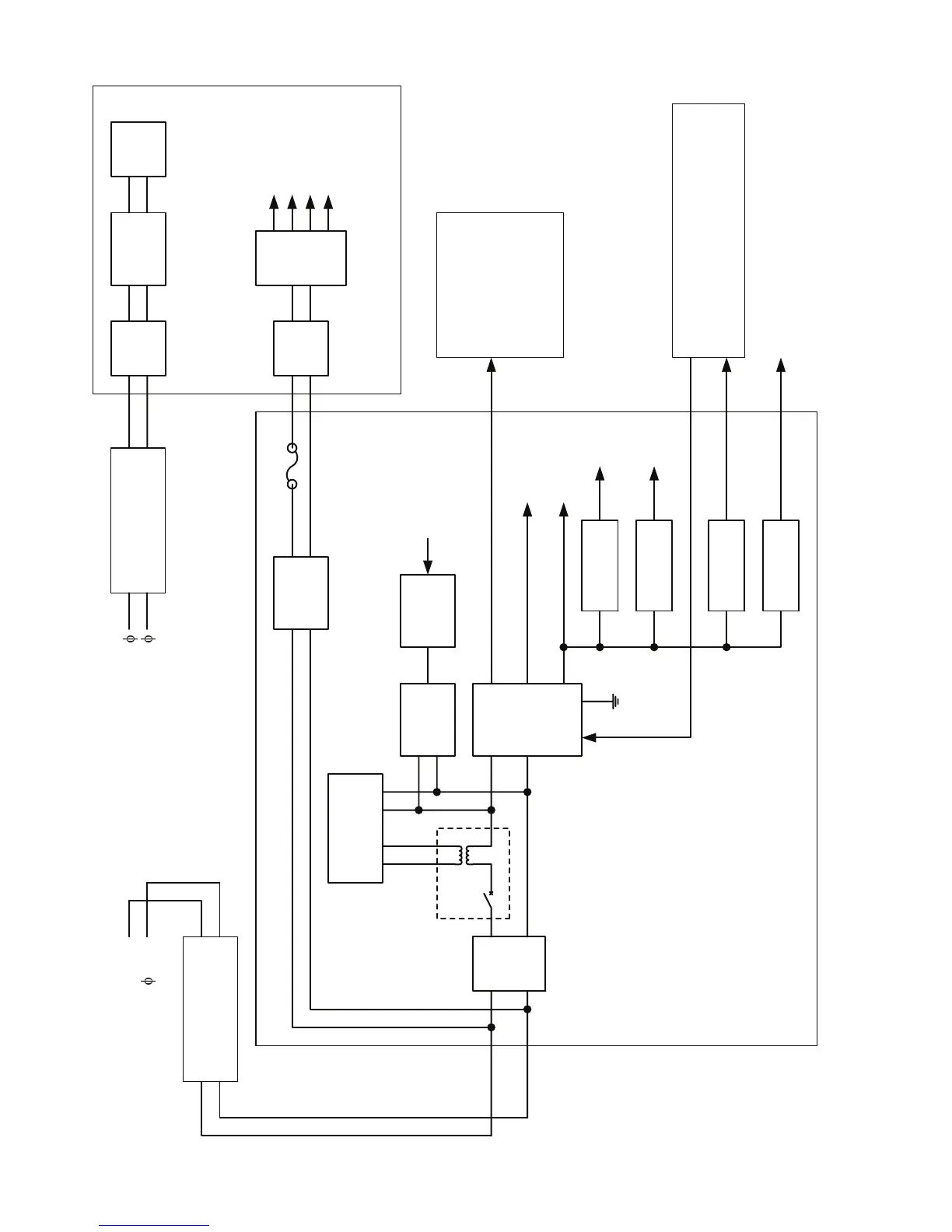
付図 8 JMA-5332-12 形レーダー電源系統図
Fig.8 Power System Diagram of JMA-5332-12 RADAR

Table of Contents

Other manuals for JRC JMA-5312-6

Questions and Answers:

Question and Answer IconNeed help?

Do you have a question about the JRC JMA-5312-6 and is the answer not in the manual?

JRC JMA-5312-6 Specifications

General IconGeneral
BrandJRC
ModelJMA-5312-6
CategoryMarine Radar
LanguageEnglish

Related product manuals