9.2 TROUBLE SHOOTING
As this radar equipment includes complicated circuits, it is necessary to request a specialist engineer for repair or
instructions for remedy if any circuit is defective.
There are also troubles by the following causes, which should be referred to in checking or repair work.
1 Poor Contact in Terminal Board of Inter-Unit Cables
a) Poor contact in terminal board
b) The cable end is not fully connected, that it, contacted with earthed another terminal.
c) Disconnected cable wire
2 Poor Contact of Connector within Unit
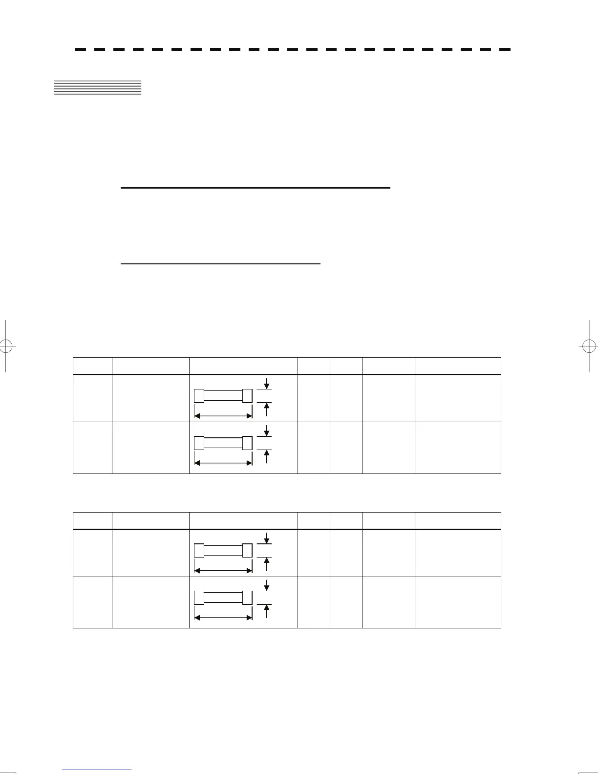
Reference: This radar equipment is provided with 9-10 standard spares.
Table 9-10 Spares (7ZXRD0026, JMA-5312-6/6HS, 7ZXRD0015, JMA-5322-7/9/6HS, JMA-5332-12)
7ZXRD0026
Name Type/Code Shape (mm) In use Spare Parts No. Location
Fuse
ST4-5AN1
(5ZFCA00050)
1 3 F2
Inside
radar process unit
Fuse
ST6-10AN1
(5ZFCA00053)
1 3 F3
Inside
radar process unit
7ZXRD0015
Name Type/Code Shape (mm) In use Spare Parts No. Location
Fuse
ST6-10AN1
(5ZFCA00053)
1 3 F2
Inside
radar process unit
Fuse
ST6-10AN1
(5ZFCA00053)
1 3 F3
Inside
radar process unit
Φ6.35
31.8
Φ6.35
31.8
Φ6.35
31.8
Φ6.35
31.8
9-7
 Loading...


