9.1 Fault Finding
y
yyyy
yyyy
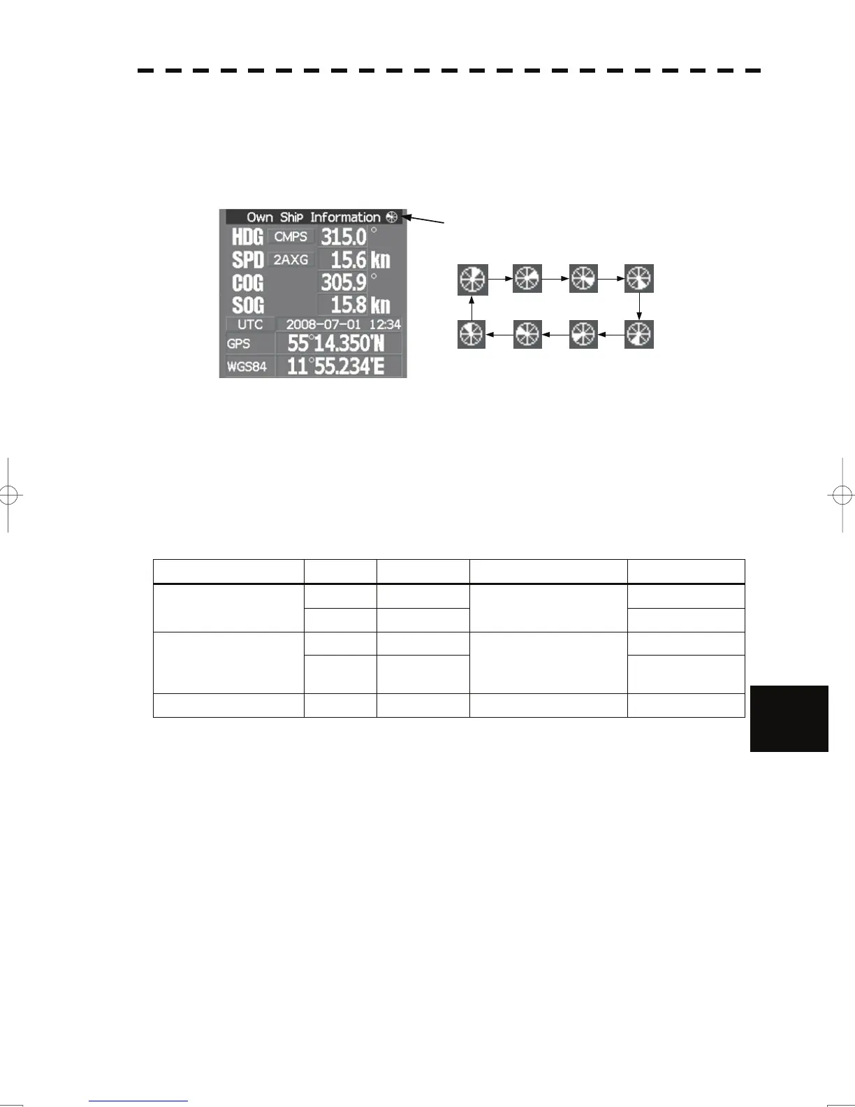
9.1.2 Operation Checking
When the system is operating, the operation status (located at the upper right of the screen) is
changing pictures.
If picture freeze occurred, turn off the system and restart the system.
Operation status
9.1.3 Fuse Checking
Melted fuses are caused by any clear cause. When a fuse is replaced, it is necessary to check the
related circuits even if there is no trouble. In checking, note that there is some dispersion in the
fusing characteristics. Table 9-9 shows a list of fuses used in the equipment.
Table 9-9 Fuse List
9
Location Parts No. Current Rating Protection Circuit Type
F2 5A ST4-5AN1 Radar process unit
(JMA-5312-6/6HS)
F3 10A
I/F circuit PC410
ST6-10AN1
F2 10A ST6-10AN1 Radar process unit
(JMA-5322-7/9/6HS,
JMA-5332-12)
F3 10A
I/F circuit PC410
ST6-10AN1
GYRO I/F unit F1 to F4 0.5A GYRO I/F circuit PC4201 MF51NR 250V 0.5
9-6

 Loading...


