1 Brief description
10
1 Brief description
The transmitter acquires the temperature through an RTD temperature probe or a thermocouple (double thermocouple). The
transmitter can also acquire standard signals such as .current 0(4) to 20 mA or voltage 0 to (1)10 V.
Additionally resistance transmitter with three-wire circuit, or resistance/potentiometer with two-wire/three-wire/four-wire circuit
can be acquired.
The output signal is galvanically isolated from the measurement input and the voltage supply.
Depending on the measurement input, different linearization variants (linear, temperature-linear, customer-specific, etc.) are
possible. Output signal: variants 0(4) to 20 mA and, alternatively, 0(2) to 10 V are available.
Process variables such as temperature or pressure are reliably emitted at the analog output and monitored for measuring over-
range and underrange.
Type 707071 is functionally expandable through the extra code, relay output and an RS485 interface.
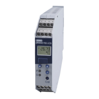
Visualization of measured values is accomplished using a dot-matrix LCD display with white backlight.
On the LCD display, it is possible to call up the connection diagram of the configured sensor input, signal output, as well as the
optional relay and interface assignment.
If a malfunction occurs the transmitter sends a defined output signal according to the recommendation of NAMUR NE 43,
which downstream systems can recognize.
The operating status is signaled optically using a two-color LED (red/green).
Smooth operation is indicated by a permanent green LED; malfunction statuses are indicated by a permanent red LED.
The sensor type, measuring range, linearization, output signal, limit values, etc. can be configured via setup program.
Alternatively, configuration is also possible via four keys on the device.
Type 707071/8-XX-058 fulfills the requirements of SIL 2, or SIL 3 in redundant use, according to DIN EN 61508 and PL c/PL d
according to DIN EN ISO 13849 as well as the requirements of DIN EN 60730-2-9.
The systematic suitability is defined at SC = 3 for HW and SW.
This means that SIL 2 or PL c for HFT = 0 (individual device) and SIL 3 or PL d for HFT = 1 (2 devices) is achieved.
The use of type 707071/8-XX-058 enables early and reliable detection of risks which could potentially result in personal inju-
ries, environmental damage, or destruction of the production plant and production materials.



 To Next Page