7 Configuration
70
7.5.4 Scaling start
Here, the output range set above is shown on the set
scaling of the signal type.
2 to 8 V is set in Chapter 5.4 "Signal flow"
4to20mA,
(the full range of the signal
type above is applied per
default)
7.5.5 Scaling end
7.5.6 Reversion output
The signal at the output can be inverted here, e.g. for a
setting of 0 °C = 0 V and 50 °C = 10 V,
through the reversion this becomes 50 °C = 0 V and
0 °C = 10 V at the output
No, Yes
7.5.7 Error signal
If, for the measured value, the value is exceeded, not
reached, or a diagnostic error occurs, the current or
voltage value set on the analog output is output as a
so-called error signal.
Negative signaling,
positive signaling,
replacement value
For signal type 4 to 20 mA
Low 3.6 or high 21.2 mA
For signal type 0 to 20 mA
Low -0.4 or high 21.2 mA
For signal type 2 to 10 V
Low 1.8 or high 10.6 V
For signal type 0 to 10 V
Low -0.2 or high 10.6 V
7.5.8 Response for limit error
Here you can select whether the analog output should
also jump to the error value if the relay switches on "1"
due to a limit value being exceeded or fallen short of.
No error signal,
error signal
7.5.9 Signal from diagnosis er-
ror
Here you can select whether the device sets the output
to an error value for all detected errors, or whether only
device-relevant errors should be considered. This
selection option only exists if there is a relay.
All errors,
device-relevant errors
k SIL operation
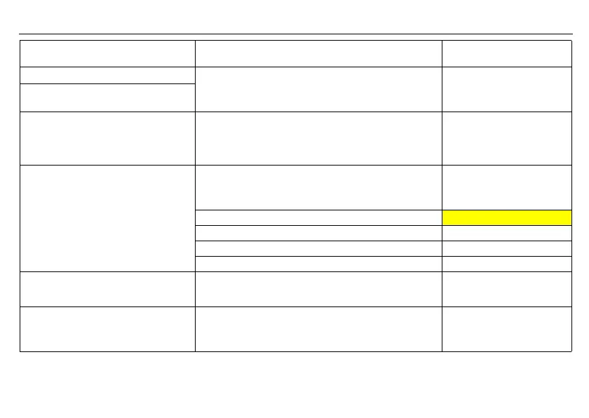
Parameter Comment
Value range
(default setting in bold)