4 Configuration parameters
54
4.2.4 Configuration - Event traces
Differential Configuration
➔Analog inputs
➔ Analog input 1—6
➔ Alarm
➔ Differential
-99999 to 0 to +99999
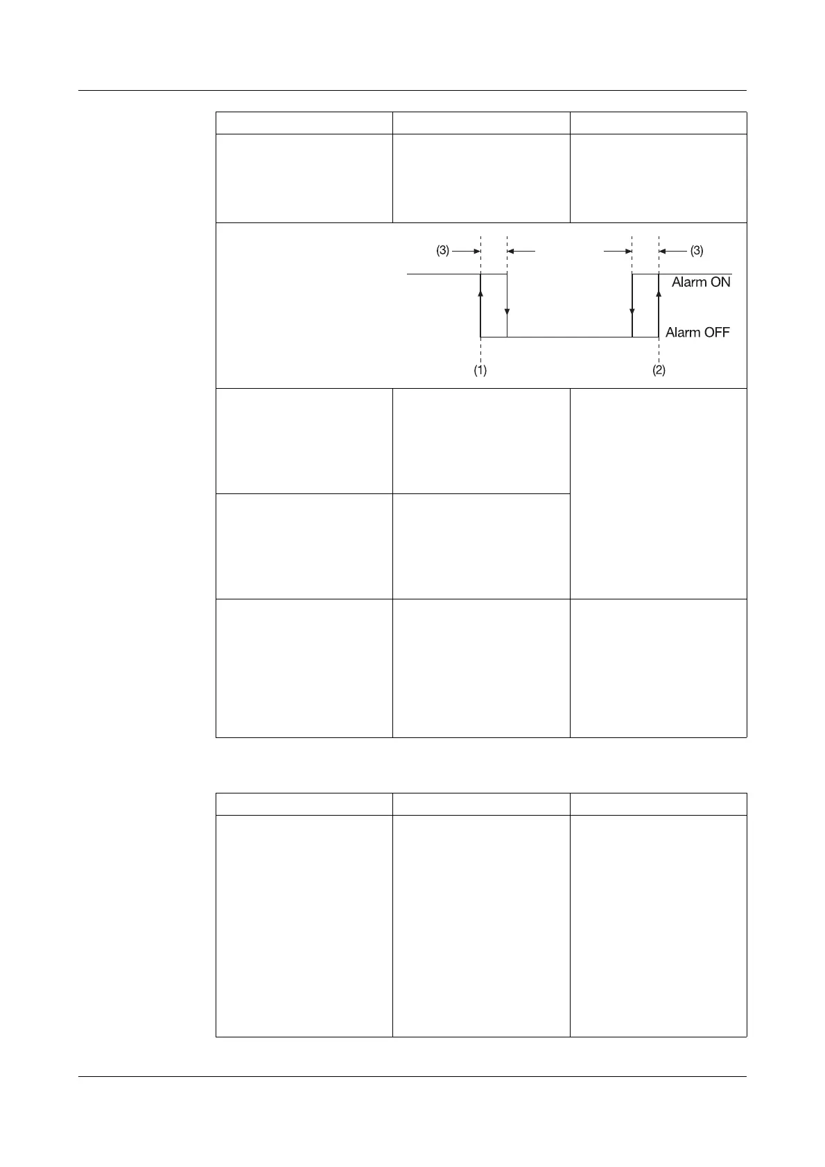
(1) = Low limit
(2) = High limit
(3) = Differential
Text low alarm Configuration
➔Analog inputs
➔ Analog input 1—6
➔ Alarm
➔ Text
low alarm
Standard text,
Text 1 — 18,
No text
v Chapter 3.5 “Event list”
v Configuration ➔ Texts,
page 61
Text high alarm Configuration
➔ Analog inputs
➔ Analog input 1—6
➔ Alarm
➔ Text
high alarm
Standard text,
Text 1 — 18,
No text
Alarm delay Configuration
➔Analog inputs
➔ Analog input 1—6
➔ Alarm
➔ Alarm
delay
0 — 32767s Alarm delay is activated at
a value of > 0.
When activated, an alarm
will only be generated
when it has been present
for at least as long as it
takes for the set time to
elapse.
Parameter Value/selection Description
Input signal Configuration
➔ Event traces
➔ Event traces 1 — 4
➔ Input signal
Off,
Logic inp1 — 4,
Logic channel 1 — 6,
Low alarm 1 — 6,
Low comb. al.,
High alarm 1 — 6,
High comb. al.,
Counter/I al. 1 — 6,
C/I comb. al.,
Comb. alarm,
Memory al.,
Error,
Modbus-Flag
The event (digital signal)
which is to be recorded is
assigned to an event trace.
Parameter Value/selection Description