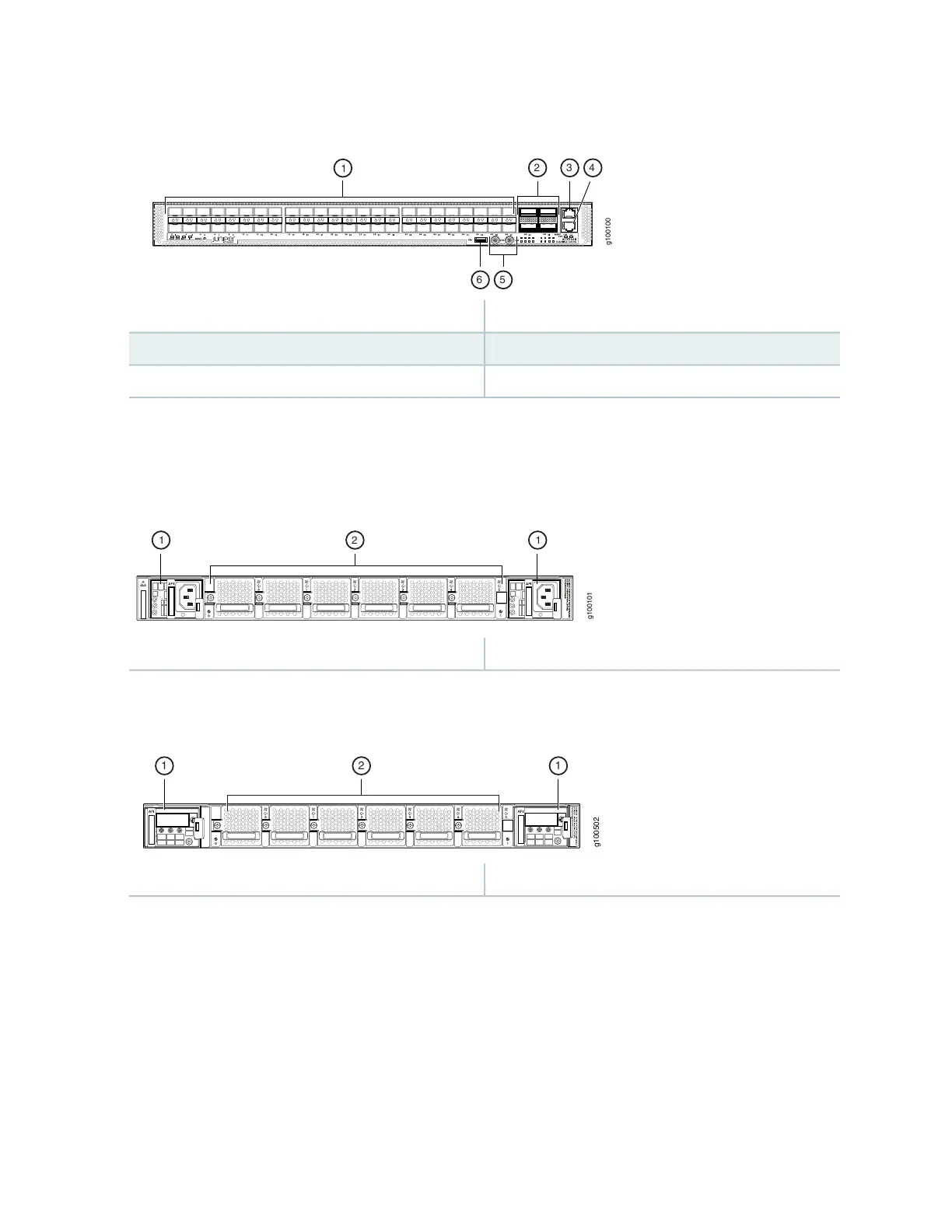
Figure 7: Front View of the ACX5448 Router
4—1— Console (CON) portSFP+ ports
5—2— PPS and 10M GPS output portsQSFP28 ports
6—3— USB portManagement (MGMT) port
Figure 8 on page 22 and Figure 9 on page 22 shows the important components on the rear of the ACX5448
routers.
Figure 8: Rear View of the AC-Powered ACX5448 Router
2—1— Fan modulesPower supply modules (AC)
Figure 9: Rear View of the DC-Powered ACX5448 Router
2—1— Fan modulesPower supply modules (DC)
The fan modules and PSMs on the ACX5448 routers are installed in slots on the rear of the chassis. The
chassis has six slots for the fan modules and two slots for the PSMs.
The six fan modules are numbered 0 through 5 from left to right. Similarly, the two PSMs are numbered
0 and 1.
Figure 10 on page 23 shows the important components on the front of the ACX5448-D router.
22