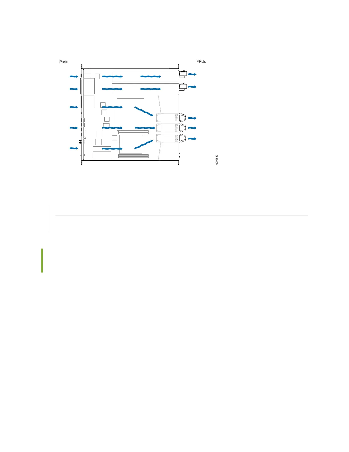
Figure 18: Airflow Through MX204 Chassis
SEE ALSO
MX204 Installation Overview | 77
MX204 Cooling System Description | 29
MX204 Router Clearance Requirements for Airflow and Hardware
Maintenance
When planning the installation site, allow sufficient clearance around the rack (see Figure 19 on page 61):
•
For the cooling system to function properly, the airflow around the chassis must be unrestricted. Allow
at least 6 in. (15.2 cm) of clearance between side-cooled routers. Allow 2.8 in. (7 cm) between the side
of the chassis and any non-heat-producing surface such as a wall.
•
For service personnel to remove and install hardware components, there must be adequate space at the
front and back of the router. At least 24 in. (61 cm) are required both in front of and behind the router.
NEBS GR-63 recommends that you allow at least 30 in. (76.2 cm) in front of the rack and 24 in. (61 cm)
behind the router.
•
To accommodate power cable bend radius at the rear of the chassis and the interface cable bend radius
at the front of the chassis, provide at least 2.75 in. (7 cm) at the rear and 3.5 in. (8.9 cm) at the front.
60