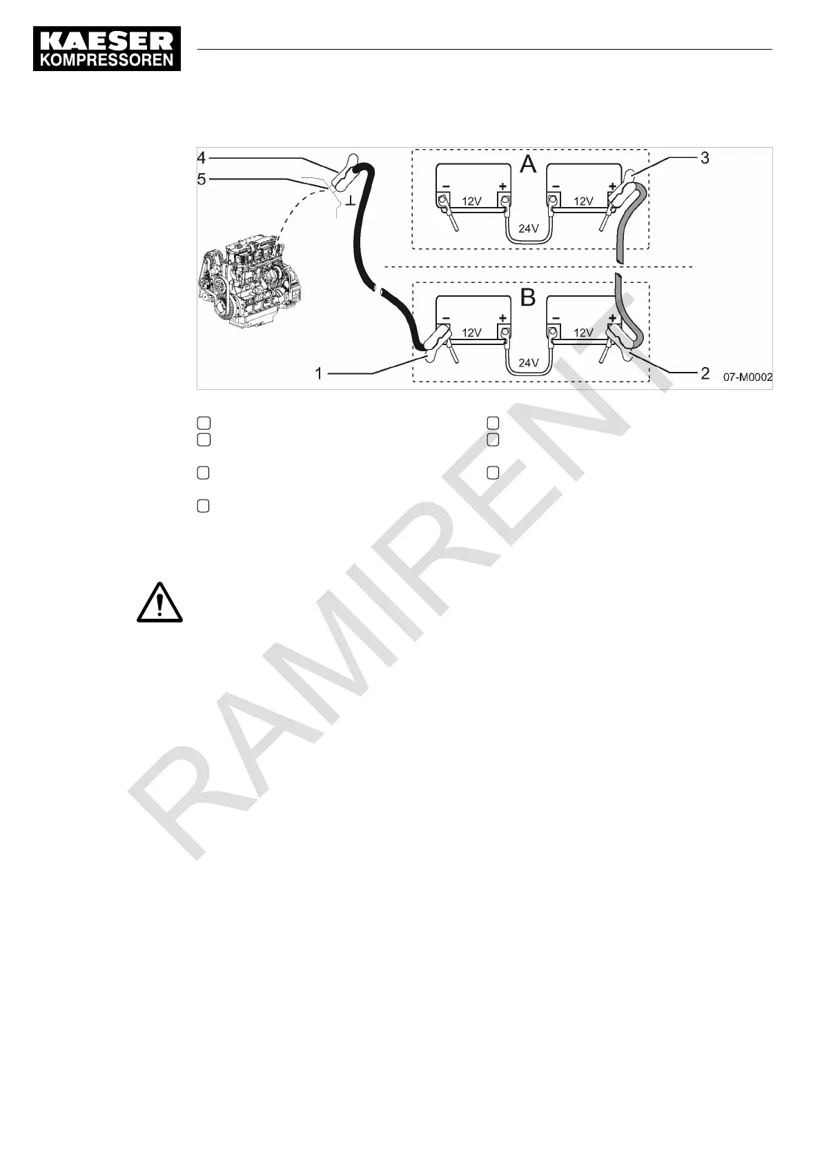
Fig. 27 Jumper cable connection diagram
A Engine battery (receiving battery)
B Assisting vehicle battery (external donor
battery)
1 Negative pole clamp (black/blue) on bat‐
tery of assisting vehicle
2 Positive pole clamp (red) on battery of as‐
sisting vehicle
3 Positive pole clamp (red) on engine battery
4 Negative pole clamp (black/blue) on engine
battery
5 Bare metal point on the engine block
(earth)
Observing the safety instructions:
1. WARNING!
Fault in starting aid process!
➤
Connect only batteries of the same voltage.
➤ Ensure that machine and assisting vehicle do not touch.
➤ Switch off all consumers prior to connecting and disconnecting the batteries.
➤ Only use standard jumper cables of sufficient diameter and with insulated terminal clamps.
➤ Observe the instructions provided with the jumper cables.
➤ Keep jumper cables away from rotating parts.
➤ Avoid short-circuits due to incorrect poling and/or bridging with tools.
➤ Do not bend over the batteries when attaching jumper cables.
➤ Do not attempt to start the machine if its batteries are frozen. Allow the batteries to thaw
first.
➤ Do not try to start the machine with a boost charger.
2. Comply with the safety instruction shown when using starting aids and starter batteries.
Preparations:
1. Park the assisting vehicle in close distance to the engine, without their bodywork touching each
other.
2. Stop the engine of the assisting vehicle.
3. Open the accesses to the batteries (remove maintenance panels/bonnet and pole caps).
4. Switch off all power consumers.
7 Initial Start-up
7.4 Low-temperature operation (winter)
60
Service manual Portable compressor
M122 No.: 9_6974 20 E