7050F 70.30.50 CK 70.30.50 CK 2140F
emaN-D tlletsre emaN .rpeg emaN .ftztesre .dtztesre
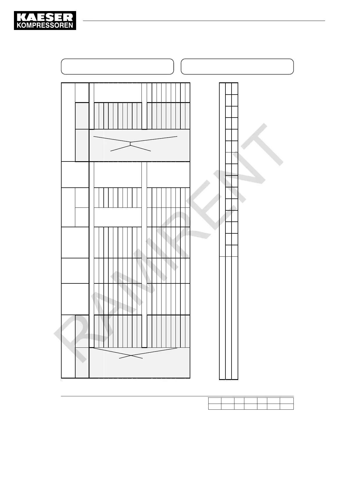
3. Technische Daten
3. Technical data
MODELL BEZEICHNUNG /
MODEL DESIGNATION
Volumenstrom
Capacity
Anschluß
Connection
Betriebsduck
Working
Pressure
Abmessungen
Dimensions
Gewicht
Weight
AUSTAUSCH-FILTERELEMENTE
FILTER REPLACEMENT CARTRIDGE
FILTER-
GRAD / GRADE
FILTER-
GEHÄUSE /
HOUSING
[m³/min]
[ ]
[max]
Höhe /
Hight
[mm]
Breite /
Width
[mm]
[kg]
FILTER-
GRAD / GRADE
FILTER-
GEHÄUSE /
HOUSING
Anzahl
Quantity
MODUL-BAUWEISE / MODULAR SYSTEM
-6
0,58 3/8“ 16 105
-6
1
-10
1,00 1/2“ 16
siehe
105
-10
1
FA -18
1,75 1/2“ 16
Kapitel
105
siehe Kapitel
E-A- -18
1
-28
2,83 3/4“ 16
„Maßzeich-
-28
1
FB -48
4,83 1“ 16
nung
133
E-B- -48
1
-71
7,10 1-1/2“ 16 164
see chapter
-71
1
FC -107
10,7 1-1/2“ 16
see chapter
164
„dimensional
E-C- -107
1
-138
13,8 2 16
„dimensional
194
drawing“
-138
1
FD -177
17,7 2-1/2“ 16
drawing“
194
E-D- -177
1
-221
22,1 2-1/2“ 13 194
-221
1
FE
BEHÄLTER-BAUWEISE / PRESSURE VESSEL
E-E-
-185
18,5 DN80 16 1025 350
-185
1
FF -283
28,3 DN80 16 1045 400
siehe Kapitel
E-F- -283
2
-354
35,4 DN80 16 1045 400
„Maßzeichnung
-185
2
FG -526
52,6 DN100 16 1085 440
E-G- -185
3
-708
70,8 DN100 16 1105 535
see chapter
-185
4
-885
88,5 DN100 16 1105 535
„dimensional
-185
5
-1420
142 DN150 16 1215 600
drawing“
-185
8
-1950
195 DN150 16 1245 720
-185
11
-2480
248 DN150 16 1245 750
-185
14
• Volumenstrom m³/h bezogen auf +20°C und 1 bar absol ut, bei Betriebsüberdruck 7 bar / Air flow m³/h based on +20°C and 1 bar absolute, at working pressure 7 bar
• Größere Betriebsdrücke auf Anfrage / Contact factory for dryers with a higher working pressure
• Filtergehäuse F-185 – F-2480: Konstruktion der Behälter entspricht der EG-Richtlinie 87/404/EEC für einfache Druckbehälter und ist mit CE-Zeichen versehen /
Filter bowls F-185 – F-2480: Vessel construction complies with directive 87/404/EEC, simple pressure vessels, and is marked with the EC symbol
Volumenstrom - Korrekturtabelle / Sizing
Minimaler Betriebsdruck / Minimum working pressure
bar
2 3 4 5 6 7 8 9 10 11 12 13 14 15 16
Korrekturfaktor / Correction factor
0,38
Bei Drücken abweichend von 7 bar berechnet sich der max. Volumenstrom wie folgt:
den Korrekturfaktor des en
tsprechenden minimalen Betriebsdruckes mit dem gewählten Volumenstrom aus o.g. Tabelle multiplizieren.
Based on
To find the maximum flow at pressures other than 7 bar:
multiply the flow (from table above) by the correction factor corresponding to the mi
nimum working pressure of the filter.
Betriebsbedingungen: Working conditions:
Min. Betriebstemperatur: +1°C Min. Working temperature: +1°C
Max. Betriebstemperatur: 66°C.
Max. Working temperature: 66°C
Min. Betriebsdruck mit automatischem Kondensatab
Min. working pressure with automatic condensate drain:
13 Annex
13.6 Operating instructions for compressed air filter (combination filter)
310
Service manual Portable compressor
M122
No.: 9_6974 20 E

 Loading...