4.2 Machine installation
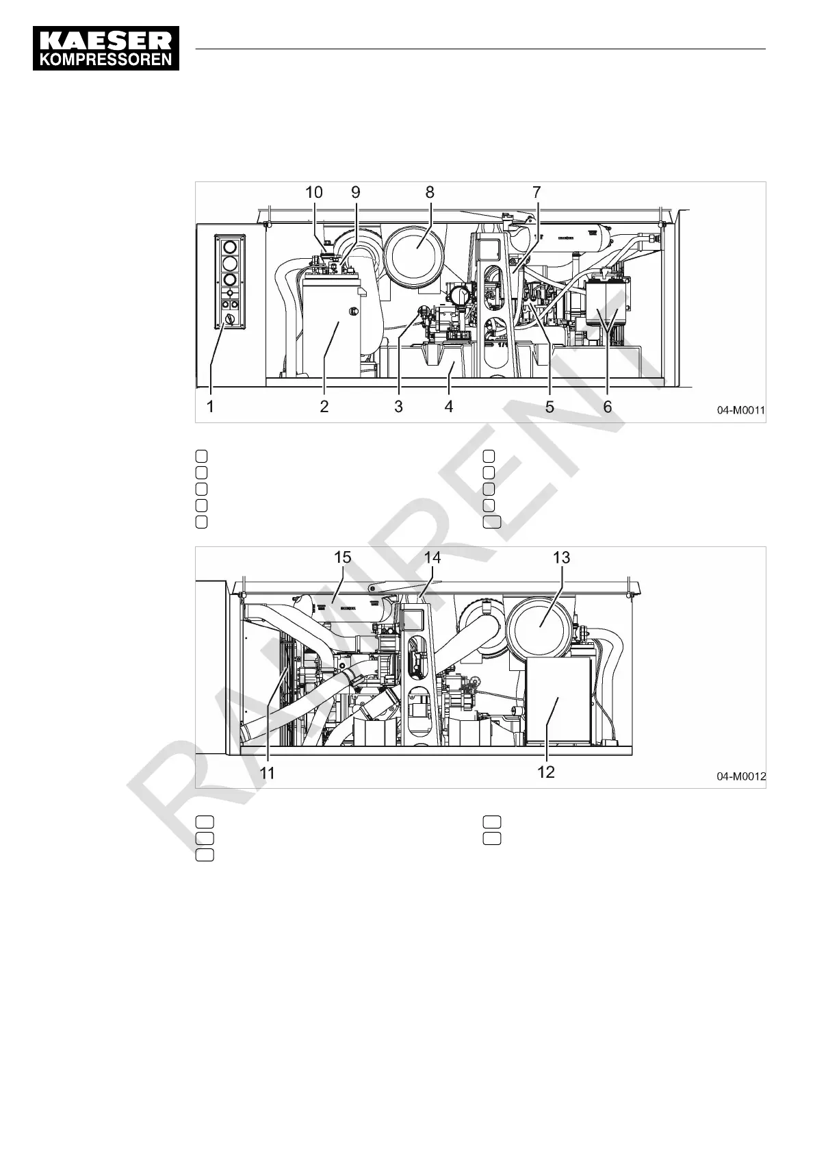
Fig. 3 Right-hand door opened
1 Instrument panel
2 Oil separator tank
3 Engine speed control cylinder
4 Fuel tank
5 Drive motor
6 Fuel filter.
7 Fuel filter with water trap
8 Engine air filter
9 Control valve with proportional controller
10 Minimum pressure/check valve
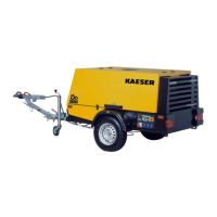
Fig. 4 Left-hand door opened
11 Fan
12 Electric control cubicle
13 Compressor air filter
14 Lifting eye
15 Coolant expansion tank
4.3 Machine function
Machine function (without options)
Item numbers correspond to the pipe and instrument flow diagram (P&ID) in chapter 13.2.
4 Design and Function
4.2 Machine installation
32
Service manual Portable compressor
M122 No.: 9_6974 20 E