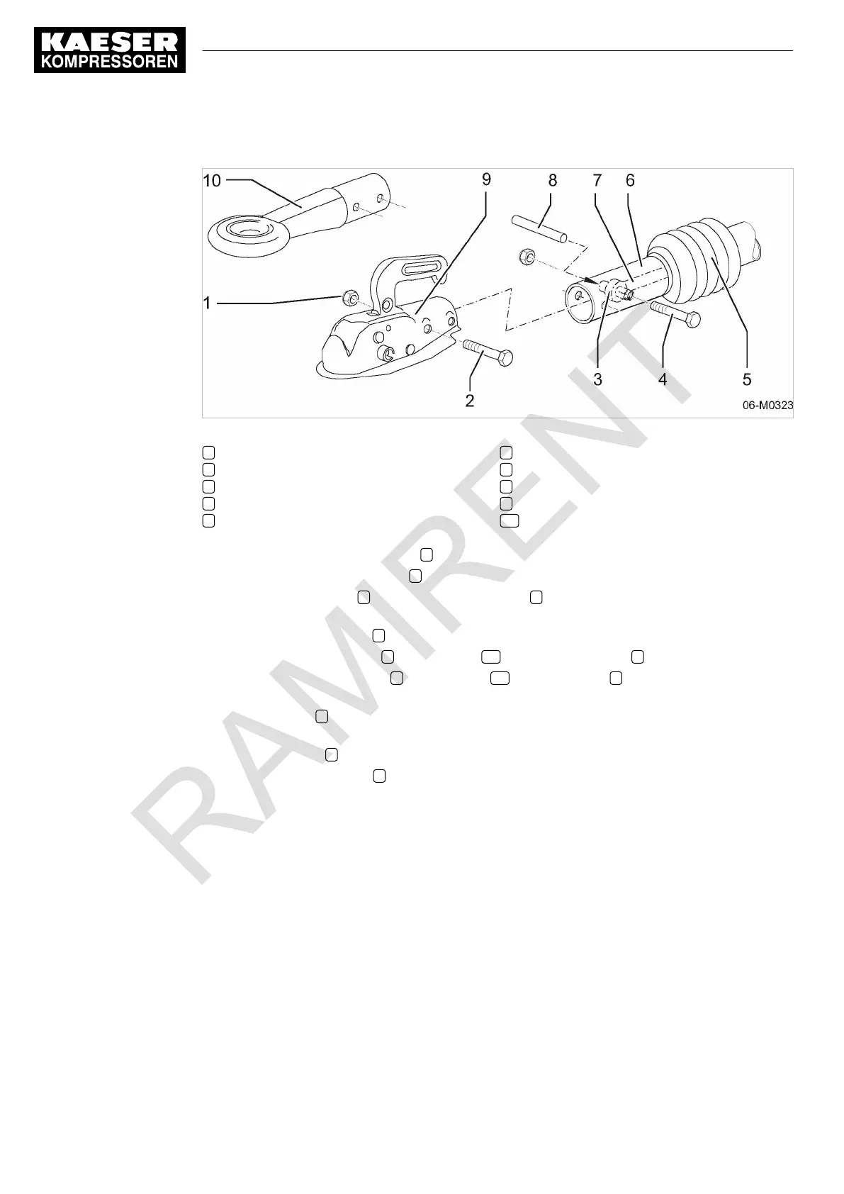
Fig. 26 Changing the towing eye (fixed height towbar, USA chassis version)
1 Self-locking hexagon nut
2 Hex-head screw
3 Damper fixing eye
4 Hex-head screw
5 Protective sleeve
6 Tension rod
7 Damper
8 Installation pin
9 Ball coupling
10 Towing eye
1. Push back the protective sleeve 5 .
2. Unscrew and remove the nuts 1 of the two screw connections.
3. Use the mounting pin 8 to beat out the rear screw 4 . Do not remove the pin in order to retain
the centring of the shock absorber in the towbar tube.
4. Remove the front screw 2 .
5. Remove the ball coupling 9 or towing eye 10 from the towbar tube 6 .
6. Push the new ball coupling 9 or towing eye 10 onto the towbar 6 until the fixating holes
match.
7. Use the screw 4 at the rear fixating hole of the towing eye/ball coupling to beat out the mount‐
ing and pin and to thread the shock absorber.
8. Insert the screw 2 through the front fixating hole.
9. Thread self-locking nuts 1 on both screws and tighten with torque wrench (see chapter 2.4.4).
10. Draw the protective sleeve over the fixings.
Checking the overrun braking mechanism
➤ Push the towbar tube in and out by hand.
If resistance is felt, the shock absorber is properly connected.
6 Installation
6.4 Adjusting the chassis
56
Service manual Portable compressor
M122 No.: 9_6974 20 E
Option sh

 Loading...