2. Couple-up the machine and tow slowly and carefully for about 500 m.
The action of towing sets the coupling mechanism to maximum closure and gives a true read‐
ing on the wear indicator.
3.
Interpret the wear indicator as follows:
Wear indicator Meaning
Green zone showing ■ Coupling in new condition.
■
Towing vehicle ball hitch wear within acceptable limits.
➤ No action necessary.
Red zone showing ■ Ball hitch wear at acceptable limit, ball coupling unworn.
■ Ball hitch in new condition; ball coupling showing increased wear.
■ Both ball and coupling showing increased wear.
■ Ball coupling is damaged.
➤ Have the ball coupling and ball hitch checked by a specialist workshop.
➤ Worn parts must be replaced.
Tab. 77 Ball coupling wear indicator
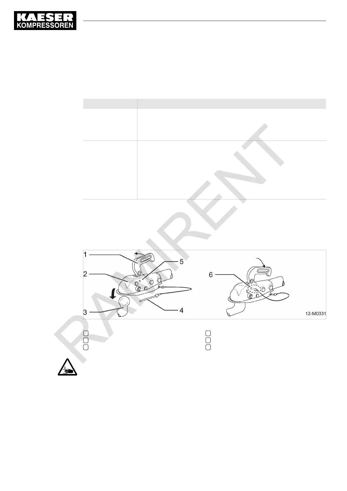
Coupling machine with ball coupling (US version):
To couple up the compressor, lower the open coupling onto the ball hitch of the towing vehicle so
that it clicks into place.
Fig. 83 Ball coupling (ALKO-USA)
1 Coupling handle
2 Ball coupling
3 Towing vehicle ball hitch
4 Safety pin
5 Mounting opening for safety pin
6 Ball hitch properly secured
1.
NOTICE!
High risk of injury by trapped fingers!
They can be trapped in the spring-loaded closing mechanism.
➤ Never place your fingers inside an open ball coupling.
➤ Wear safety gloves.
2. Check if the security pin is removed from the coupling and draw it out if not.
3. Pull up the coupling handle.
The coupling opens.
12 Decommissioning, Storage and Transport
12.2 Transport
230
Service manual Portable compressor
M122
No.: 9_6974 20 E
Option sh

 Loading...