65
BiSS / EnDat 2.2 - Encoder Connections
• Max. Load capacity depending on Voltage Supply
• Max. Load capacity at +5.25V = 300 mA; 24V = 1A. The specied current is reduced by the
current taken from the second encoder interface X3B interface (see Section 3.3.9).
Biss/EnDat 2.2
Pre-manufactured BiSS/EnDat 2.2 cables offer the best solution due to high clock frequencies and
protection against noise and disturbance while saving installation time. The maximum length is
50m.
Cable Part Number
00F50C1-B0xx xx = length in meters, 10 = 10 meters
Mating Connector
0090912-004U for encoder (solder type)
Running in Conduit
When this cable must be pulled through metallic conduit, it is necessary to over size the
conduit! Use of a 1 1/2-inch trade size conduit will allow the connectors to pass without removal of
the connectors. Cutting the cable, or removal of the connectors or their housings voids the warranty
and will result in problems with electrical noise after the fact.
BiSS / EnDat 2.2
Drive connection X3A
Screw Terminal Strip
Circular connector on
EnDat 2.2/BiSS encoder.
3 CLOCK+ Green
4 CLOCK- Yellow
6 +5.25V Red
8 COM Black
Shield wire tied to housing
Wire color
1 DATA+ Pink
2 DATA- Blue
Shield wire tied to housing
which is earth ground.
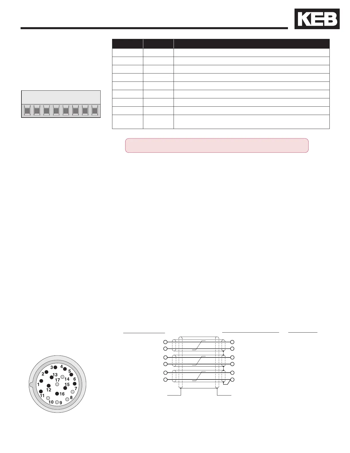
Encoder pin-out
X3A pin-out channel 1
CLOCK+ 8
CLOCK- 9
DATA + 14
DATA- 17
Note: Inner pair shields are tied to 0V (com),
not earth ground!
Pin No. Signal Description
1 DATA + Data Channel +
2 DATA - Data Channel -
3 CLOCK + Clock Channel +
4 CLOCK - Clock Channel -
5 -
6 5V 5.25V voltage output for encoder supply
7 24V 24V voltage output for encoder supply
8 COM Reference potential for voltage supply
- GND Function earth is not available at the terminal block and must be
connected at appropriate place at the unit.
ONLY when the inverter is switched off and the voltage supply is discon-
nected may the feedback connectors be removed or connected!
+5.25V 7
COM 10

 Loading...


