Spot mean measurements
Spot mean measurements sample a portion of the amplitude and a portion of the base level (see
Spot mean measurement timing (on page 4-27)). The portions to be sampled are specified as a
percentage. Note that you can return an individual spot mean for each pulse (see Spot mean discrete
readings (on page 4-24)), or have a single spot mean for all NumPulses (see Spot mean average
readings (on page 4-25)).
If you enable both amplitude and base spot means, each pulse has two voltage measurements and
two current measurements (see pulse_fetch).
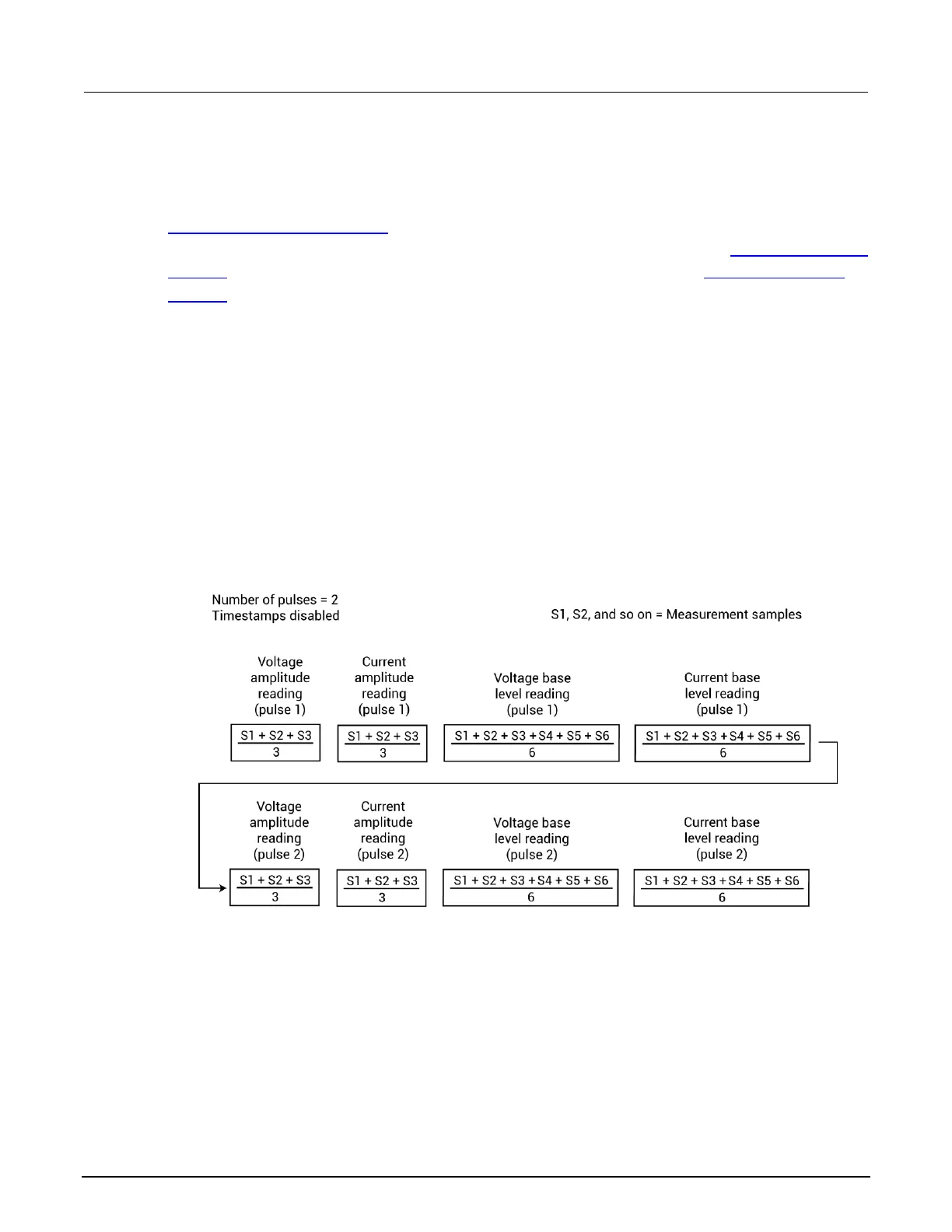
Spot mean discrete readings
The averaged voltage and current readings for every sampled pulse period are returned in a single
data set. The figure below shows how spot mean discrete readings are returned as a data set for two
pulse periods. With all voltage and current readings enabled, four readings are returned for each
pulse. The measured samples are averaged to yield the mean average readings. When time stamps
are enabled, a time stamp is included in the data set after each mean reading.
Figure 93: Returned data set for spot mean discrete readings
 Loading...


