Connection schematic
The hardware connections from the output terminals of the PMU and the two RPMs to the MOSFET
are shown in the following figures.
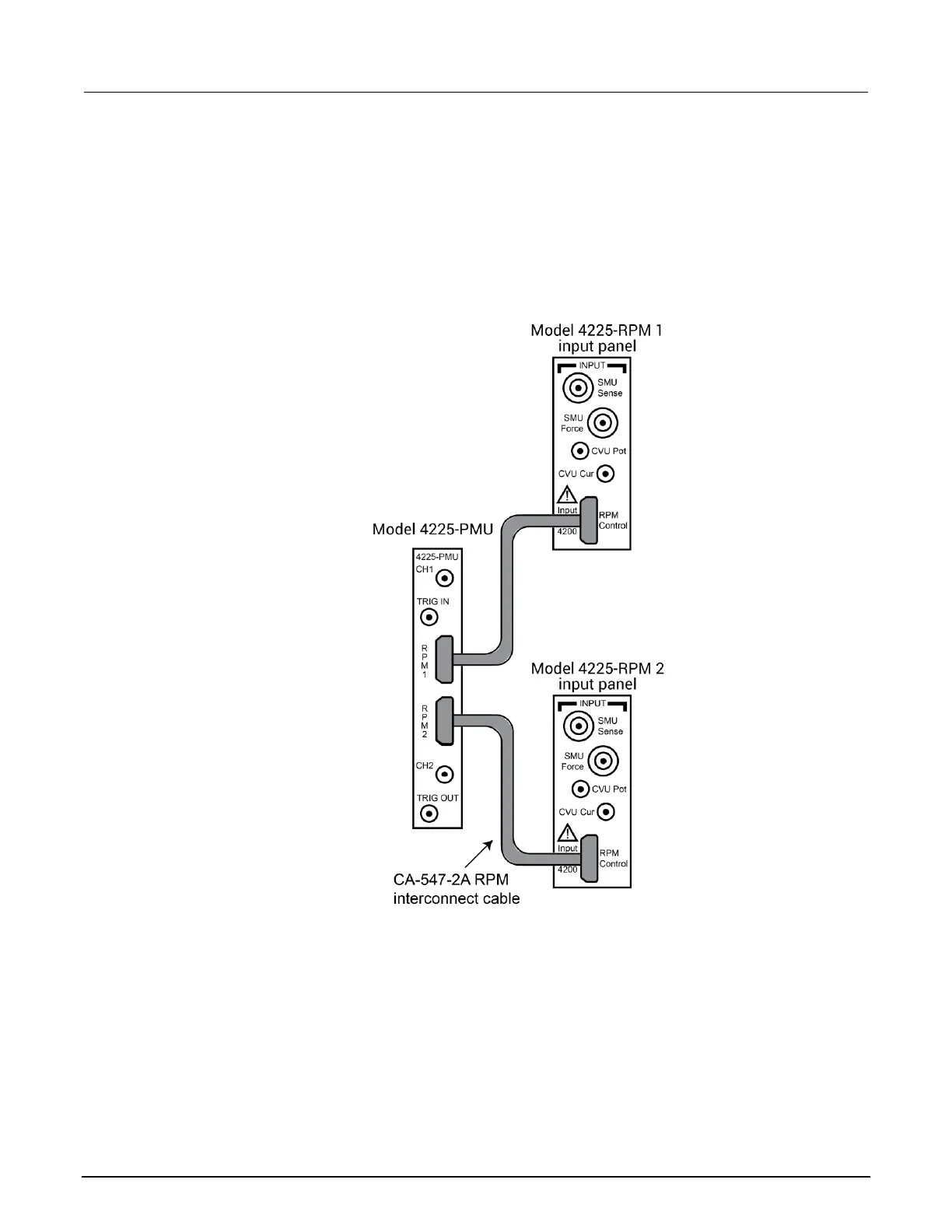
Connect one CA-547-2A RPM interconnect cable from each PMU channel to the appropriate RPM.
Figure 142: Connections from the PMU to the RPM inputs
At the output of each RPM, connect the triaxial to BNC adapter, BNC to SMA adapter, and finally the
SMA-to-SMA cable.
Connect the SMA cables to either probes or a test fixture that is connected to the MOSFET. RPM1 is
connected to the gate of the MOSFET and RPM2 is connected to the drain of the MOSFET.
The shields of the SMA cables are the PMU LO connection and must be connected to the source and
bulk terminals of the MOSFET. The shields of the two SMA cables should be connected together as
close as possible to the device.
 Loading...


