Figure 79: Simplified circuits of the PGU and PMU
PMU block diagram
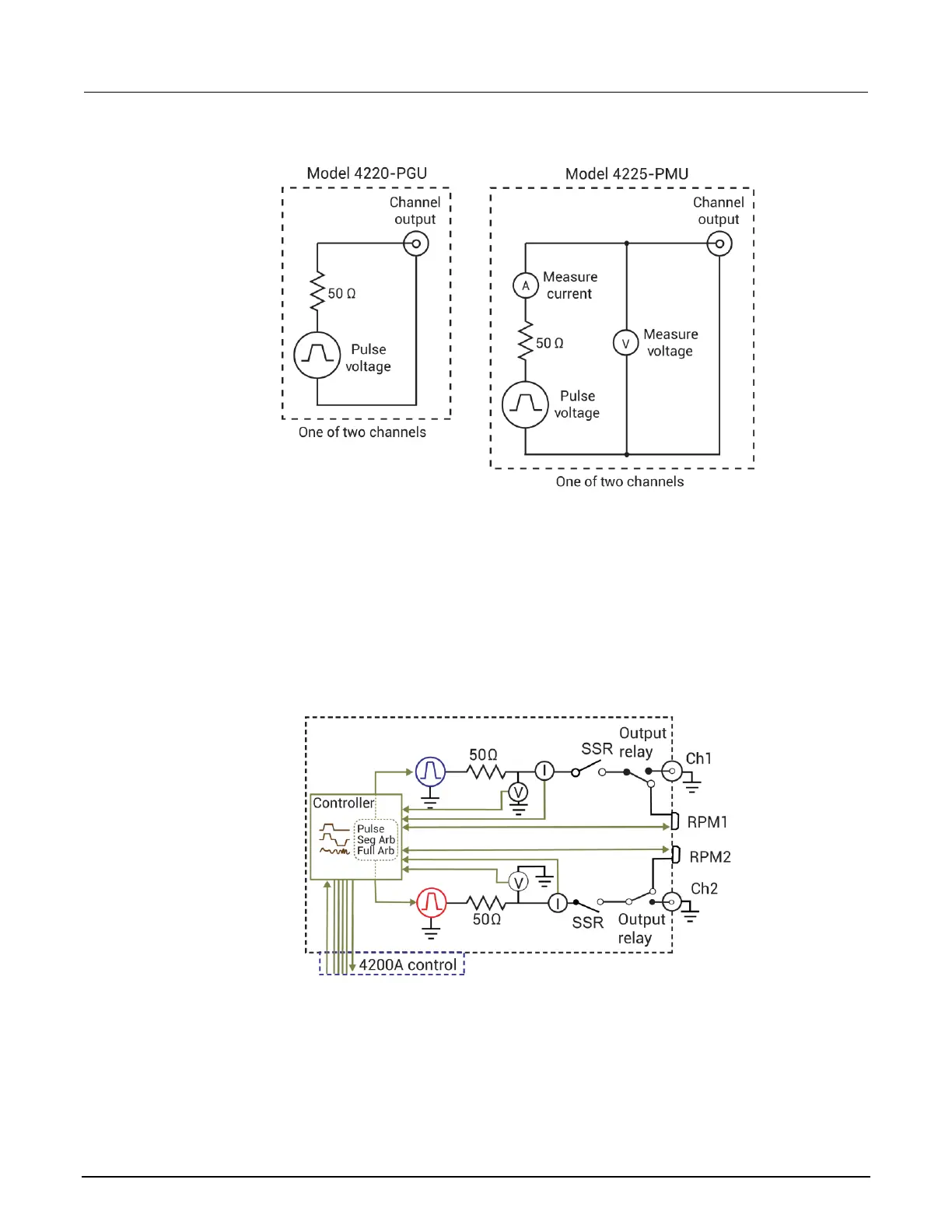
The following figure shows the block diagram of the PMU. Each channel has two dedicated A/D
converters to simultaneously measure current and voltage. The PMU controller controls the two
output channels and any RPMs connected to it. The solid-state relays (SSRs) are high-speed and are
used to test flash memory. The mechanical output relays are low-leakage. The block diagram for the
PGU is similar, except it does not have measure capability and does not have the RPM connectors.
Figure 80: 4225-PMU block diagram
 Loading...


