Using a switch matrix
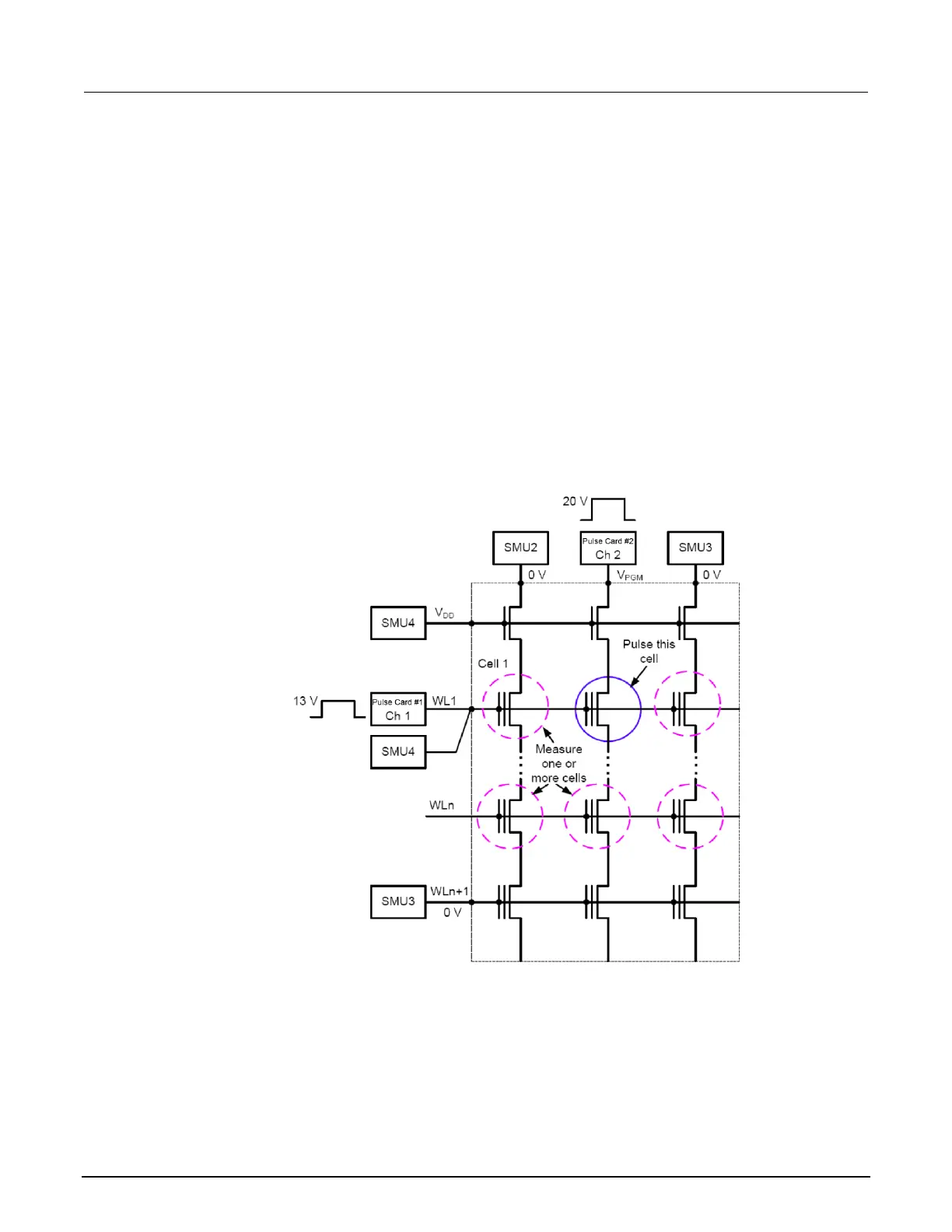
A limitation of the no-switch, direct connect test configuration shown in the figure below is that only
three devices can be measured. The test would have to be manually reconfigured or re-cabled to test
other devices.
Without a switch matrix, the number of adjacent cells that can be measured is limited. Therefore, it is
recommended that a switch matrix be used for disturb testing.
Using a switch matrix allows the flexibility of routing pulse and DC signals without having to make
connection changes. Also, this type of structure uses a multi-pin probe card, which provides an
additional opportunity for mapping test resources to DUT pins. For example, a SMU can be shared
across multiple device terminals where the required voltage is the same.
Figure 168: Disturb testing - configuration to test a single device
 Loading...


