34410A/11A/L4411A User’s Guide 117
Measurement Tutorial 4
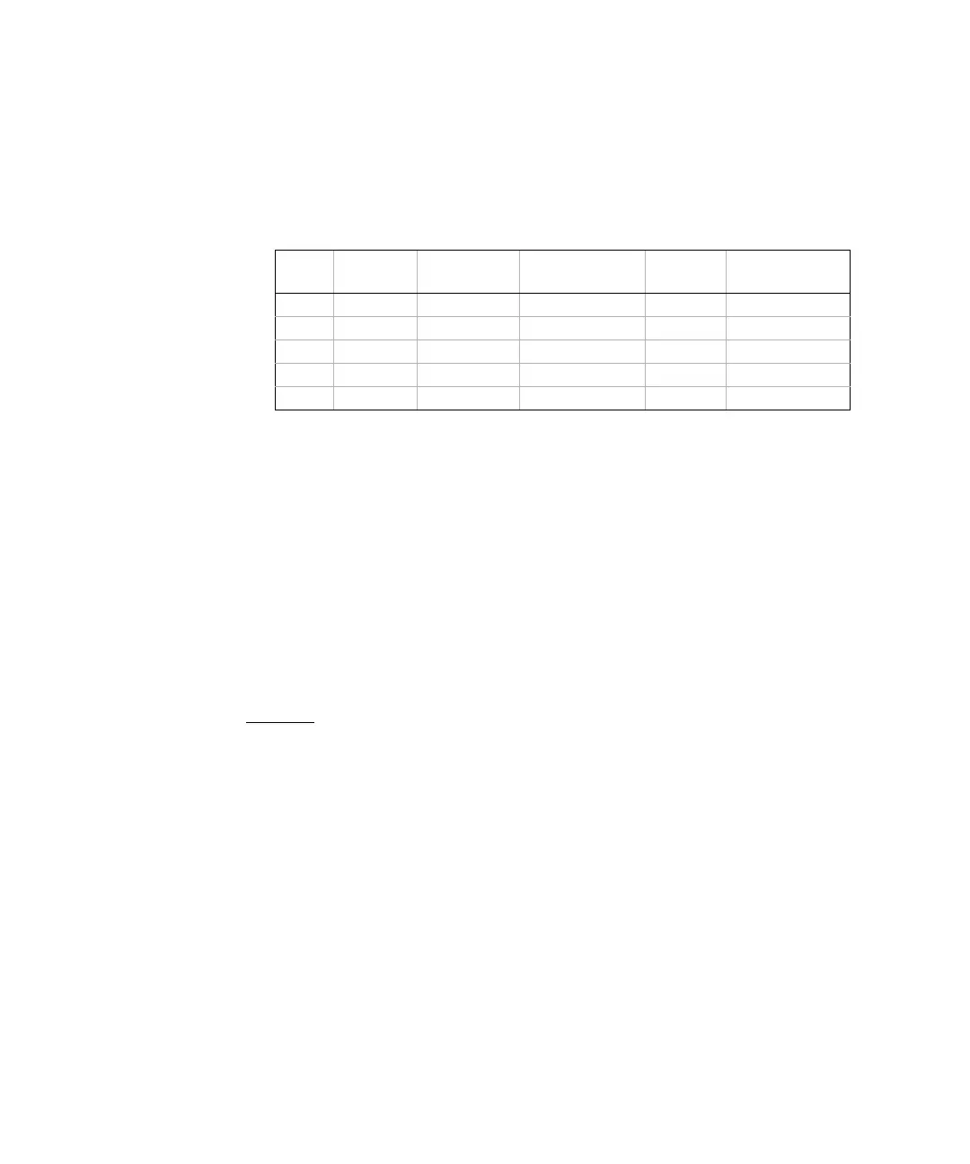
The incremental times (or “sample times”) as well as the width of the “short apertures”,
vary by range, in order to minimize noise and increase reading accuracy. The following
table lists the current amplitude, peak voltage and average dc voltage developed across
the capacitor during the measurement.
These values all vary by range. Control of the peak voltage across the capacitor is
important in some cases, such as when measuring larger electrolytic capacitors.
The values of capacitance and loss resistance measured with the multimeter may differ
from the values measured using an LCR meter. This is to be expected since this is
esentially a dc measurement method, while LCR measurement uses applied frequencies
anywhere from 100 Hz to 100 kHz. In most cases, neither method measures the
capacitor at its exact frequency of application.
The 34410A/11A/L4411A provides five capacitance ranges from 1 nF to 10
μF. The
voltage developed across the capacitor being measured is limited to less than 10 V. The
multimeter’s measurement accuracy is 0.4% of the reading, + 0.1% of the range in use
(except for the 1 nF range, for which the accuracy is 0.5% of the reading, + 0.5% of the
range).
Example:
For a 5 nF capacitor, measured using the 10 nF range, the accuracy is (0.4%)(5
nF) + (0.1%)(10 nF) = 30 pF total error possible.
For the best accuracy, take a zero null measurement with open probes, to null out the test
lead capacitance, before connecting the probes across the capacitor to be measured.
Temperature Measurements
The multimeter allows the measurement of temperature by measurement of the
temperature sensitive resistance of two different "Probe" types: the resistance
temperature detector (RTD) of 0.00385/
o
C; and thermistors of
2.2 KΩ, 5 KΩ, or 10 KΩ). There are a number of measurement parameter and technique
choices available to you, and these affect various aspects of the measurement:
• Temperature range and resolution can direct the probe–type choice.
Range Current
Source
Reading Rate
at full scale
Reading Rate @
10% of full scale
Applied
Voltage
Approx. dc bias
@ full scale
1 nF 500nA 5/second 12/second 5V 2V
10 nF 1μA 5/second 24/second 5V 2V
100 nF 10μA 5/second 26/second 4V 2V
1 μF10μA 2/second 18/second 1.5V 1V
10 μF 100μA 0.3/second 2.5/second 1.5V 1V