124 34410A/11A/L4411A User’s Guide
4 Measurement Tutorial
low–impedance source. You can reduce the high–frequency impedance of a source by
placing a capacitor in parallel with the multimeter's input terminals. You may have to
experiment to determine the correct capacitor value for your application.
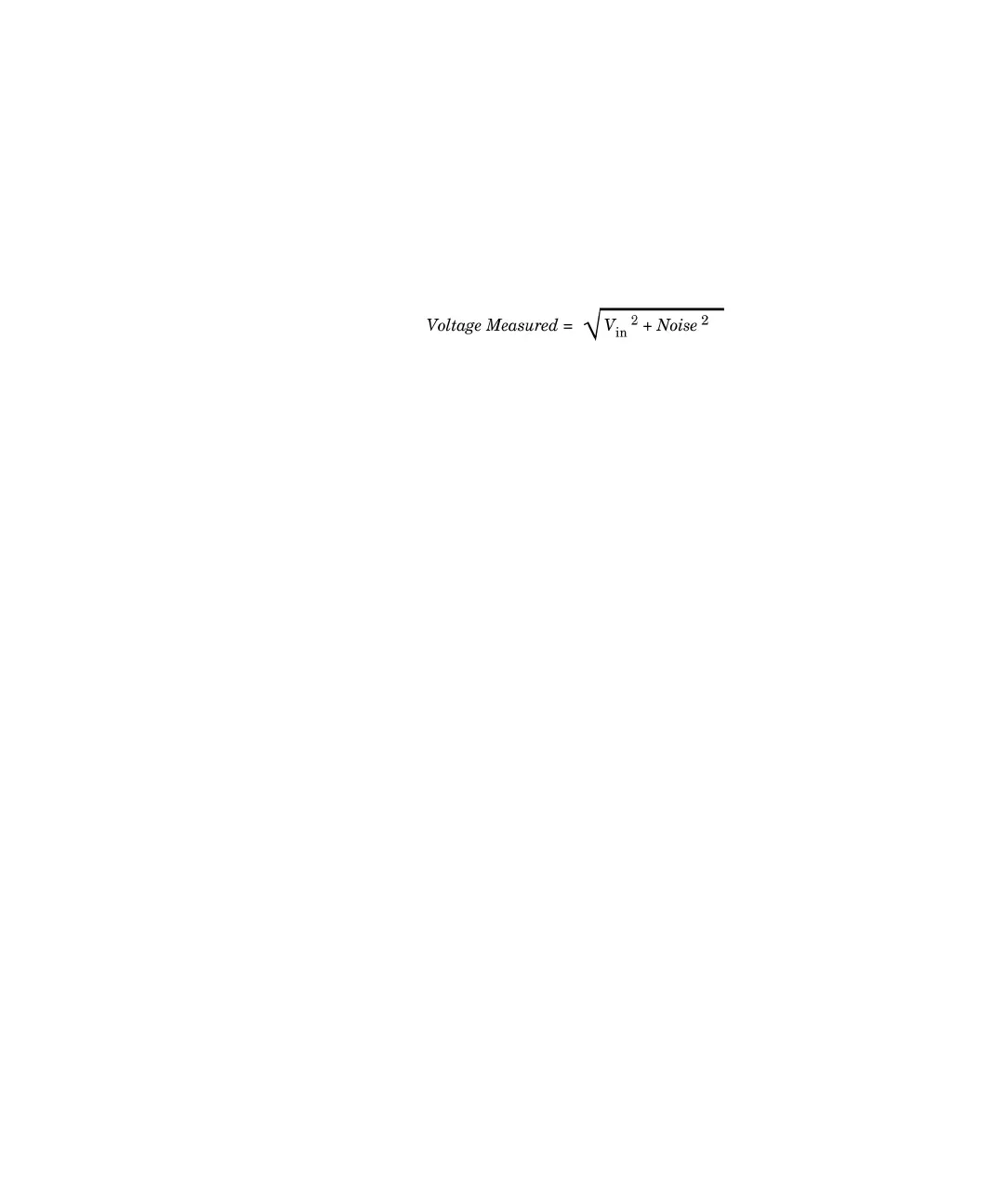
Most extraneous noise is not correlated with the input signal. You can determine the
error as shown below.
Correlated noise, while rare, is especially detrimental. Correlated noise always adds
directly to the input signal. Measuring a low–level signal with the same frequency as the
local power line is a common situation that is prone to this error.
Common Mode Errors
Errors are generated when the multimeter's input LO terminal is driven with an ac
voltage relative to earth. The most common situation where unnecessary common mode
voltages are created is when the output of an ac calibrator is connected to the multimeter
"backwards." Ideally, a multimeter reads the same regardless of how the source is
connected. Both source and multimeter effects can degrade this ideal situation. Because
of the capacitance between the input LO terminal and earth (approximately 200 pF), the
source will experience different loading depending on how the input is applied. The
magnitude of the error is dependent upon the source's response to this loading.
The multimeter's measurement circuitry, while extensively shielded, responds
differently in the backward input case due to slight differences in stray capacitance to
earth. The multimeter's errors are greatest for high–voltage, high–frequency inputs.
Typically, the multimeter exhibits about 0.06% additional error for a 100 V, 100 kHz
reverse input. You can use the grounding techniques described for dc common mode
problems to minimize ac common mode voltages.
Leakage Current Errors
The multimeter's input capacitance will "charge up" due to input bias currents when the
terminals are open–circuited (if the input resistance is >10 GΩ). The multimeter's
measuring circuitry exhibits approximately 30pA of input bias current for ambient
temperatures from 0 °C to 30 °C. Bias current doubles (x2) for every 8 °C change in
ambient temperature above 30 °C. This current generates small voltage offsets