78 34410A/11A/L4411A User’s Guide
2 Features and Functions
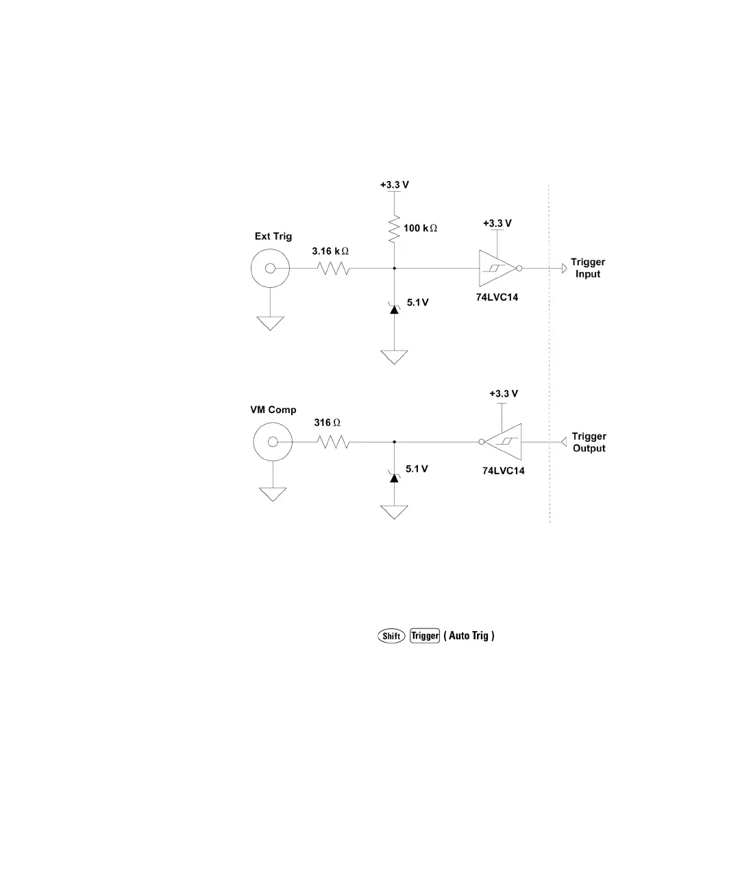
Trigger Input/Output Circuitry. The following diagram is representative of the
34410A/11A/L4411A trigger input and output circuitry. In each circuit, a Schmitt
Trigger (74LVC14) is used to prevent multiple triggers.
Trigger Slope
You may select whether the multimeter uses the rising edge (POS) or falling edge
(NEG) of the external trigger signal to trigger a reading, or (independently) for the
voltmeter complete output signal. The default for both is NEG.
• Front Panel Operation: Press
TRIGGER > SETUP > N SAMPLES > TRIG DELAY > TRIG SLOPE > VMC
SLOPE
For each of TRIG SLOPE and VMC SLOPE, you can select either NEG or POS:
• TRIG SLOPE sets the slope of the Ext Trig input signal (NEG or POS).
• VMC SLOPE sets the slope of the VM Comp output signal (NEG or POS).
Then step through or exit the configuration menu.