80 6000 X-Series Oscilloscopes Service Guide
4 Troubleshooting
To check power to the front panel (AutoProbe) interfaces
This procedure checks the power supplies from the power board to the front panel
keyboard (for the AutoProbe interface. Values outside the expected range help
identify bad assemblies.
1 Follow the instructions in “To prepare for internal assembly
troubleshooting" on page 69.
2 Connect the negative lead of the multimeter to a ground point on the
oscilloscope.
3 Connect the power cord, and turn on the oscilloscope.
4 First check the bulk power supply voltage: “To check the power supply DC
output" on page 73
5 Next, check the supplies from the power board to the front panel AutoProbe
interfaces:
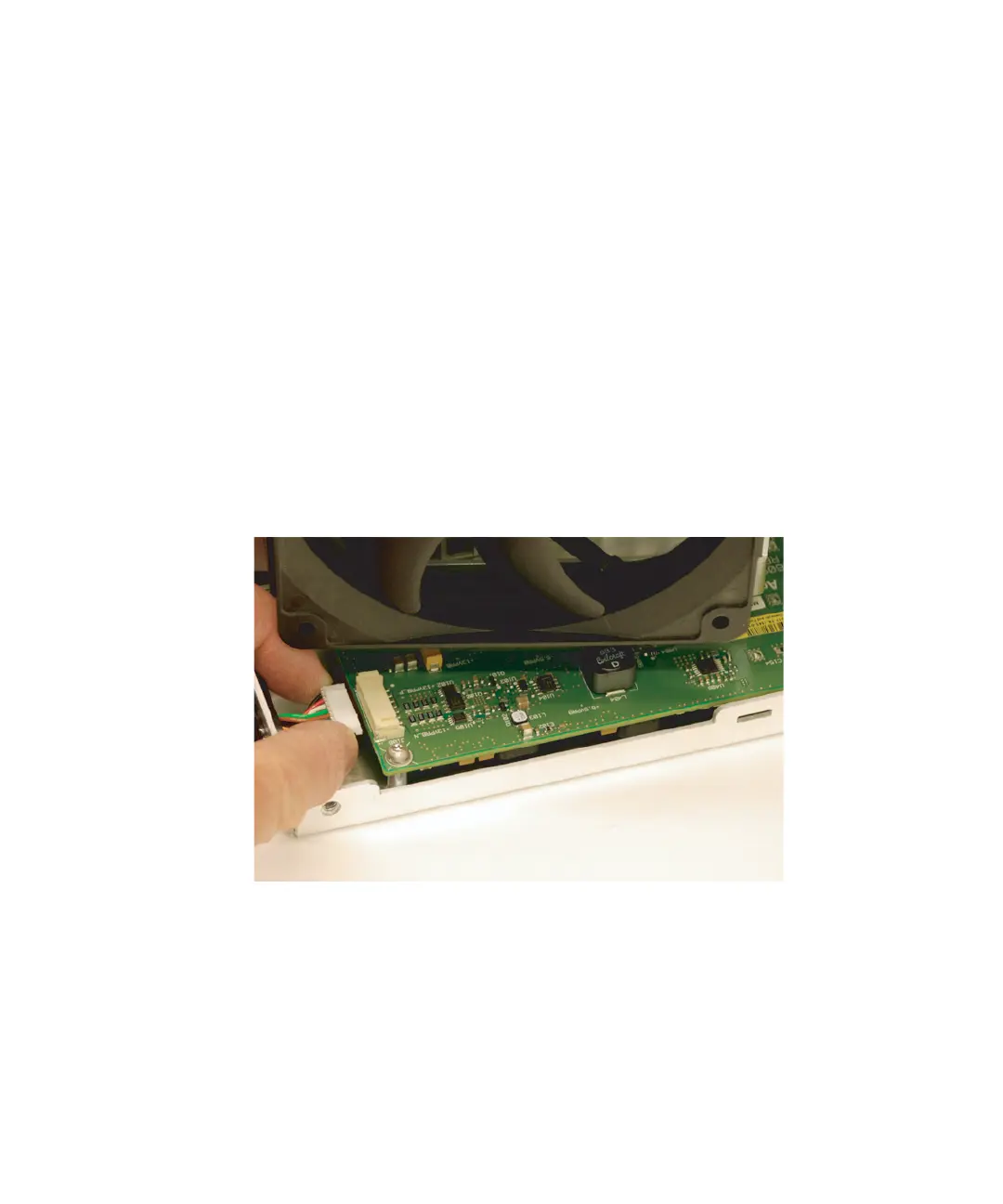
Figure 17 Location of the J106 probe power connector

 Loading...


