20
Hardware
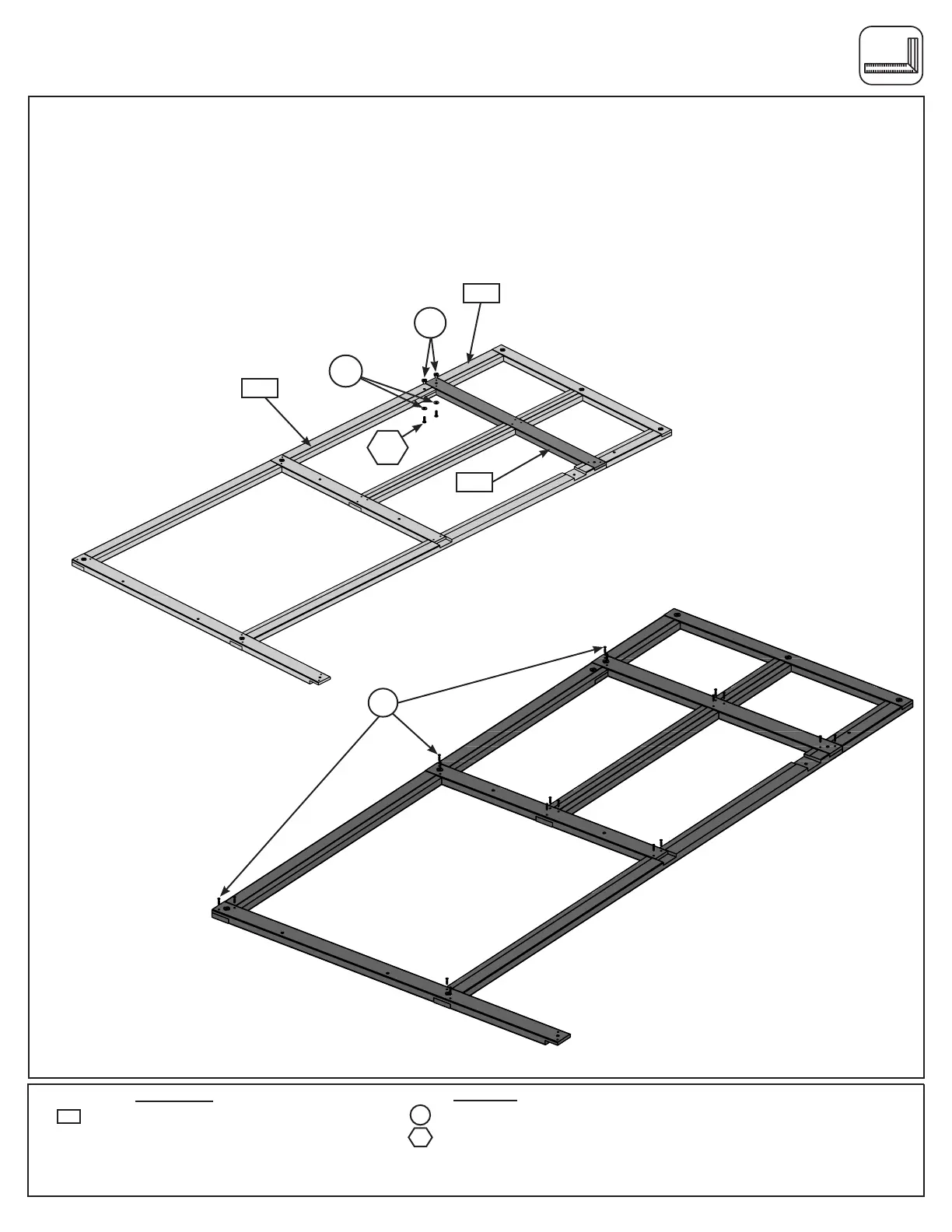
Step 2: Front Wall Assembly
Part 2
E: Bring the top and bottom of the frame assemblies together as shown in g. 2.3. Place 1 (9353) Cross Support
Top across the assemblies where they meet. Attach (9353) Cross Support Top to (9368) Right Upright Front using
1 (WB1) 5/16 x 1” Wafer Bolt (with at washer and t-nut) and install a second (WB1) 5/16 x 1” Wafer Bolt (with at
washer and t-nut) to attach (9375) Front Right Post to (9368) Right Upright Front. (g. 2.3)
F: Make sure that the assembly is square and then install 18 (S30) #8 x 1- 1/16” Wood Screws in the locations
shown in g. 2.4.
G: Tighten all bolts.
Fig. 2.4
S30
x 18
x 2
Hardware
18 x #8 x 1-1/16” Wood Screw
S30
Fig. 2.3
9353
WB1
9368
9375
9353
1 x Cross Support -Top 1-1/4 x 3 x 42-15/16”
Wood Parts
2 x 5/16 x 1” Wafer Bolt
(FW2, TN2)
WB1
TN2
FW2