88
V5, pg 180, fig 32.1 update image
* take inside view
from an existing
instruction
* take inside view
from an existing
instruction
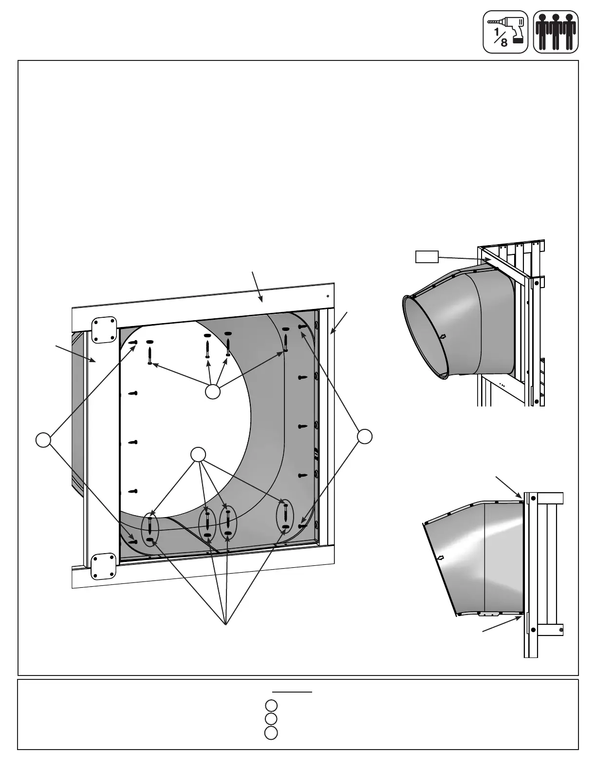
Step 42: Attach Flange Assembly to Fort
Hardware
14 x #12 x 1” Pan Screw
4 x #12 x 2” Pan Screw
8 x #12 Screw Bezel
S7
S6
FW6
ush to top of
the (9214) End
Slide Panel
ush to bottom
of the (9214) End
Slide Panel
Fig. 42.1
Fig. 42.3
Fig. 42.2
Outside View
Inside View
A: With a helper place the Flange Assembly ush to the top opening in (9214) End Slide Panel as shown in g.
42.1 & 42.2, then pre-drill 1/8” pilot holes in the bottom 4 mounting locations (approximate spots where circles
are on gure), making sure the pre-drilled holes are a minimum of 2.5 cm (1”) deep. (g. 42.1)
B: Attach Flange Assembly to bottom of (9214) End Slide Panel opening using 4 (S7) #12 x 2” Pan Screws
(with #12 Screw Bezel) in the pre-drilled holes. (g. 42.1) Make sure the at surfaces of the Flange Assembly
are ush to the (9214) End Slide Panel as shown in g. 42.3.
C: Attach the Flange Assembly ush to top of (9214) End Slide Panel opening using 4 (S6) #12 x 1” Pan
Screws (with #12 Screw Bezel) as shown in g. 42.1 and to both sides using 5 (S6) #12 x 1” Pan Screws per
side. (g. 42.1)
9214
Lower SL Insert
the 4 holes need
to be pre-drilled
side
side
S6
x 5
w/ #12
Screw Bezel
w/ #12
Screw Bezel
S7
S6
x 5
S6
 Loading...