34
2 x Side Floor Joist 1-1/2 x 1-1/2 x 62-13/64”
2 x Side Joist 1-1/2 x 1-1/2 x 21-15/32”
Wood Parts
9356
9382
8 x #8 x 2-1/2” Wood Screw
8 x 5/16 x 2-5/8” Wafer Bolt
(FW2, TN2)
Hardware
S3
WB10
front wall
hidden
for
clarity
NOTE hole
orientation
Fig. 7.5
9356
Panel
or
5/8” (16mm)
Fig. 7.4
9382
front wall
hidden
for
clarity
front wall hidden
for clarity
Fig. 7.2
9356
9002
9382
9451
9362
S3
x 4 per
side
x 4 per
side
WB10
9356
Fig. 7.3
9356
9382
S3
WB10
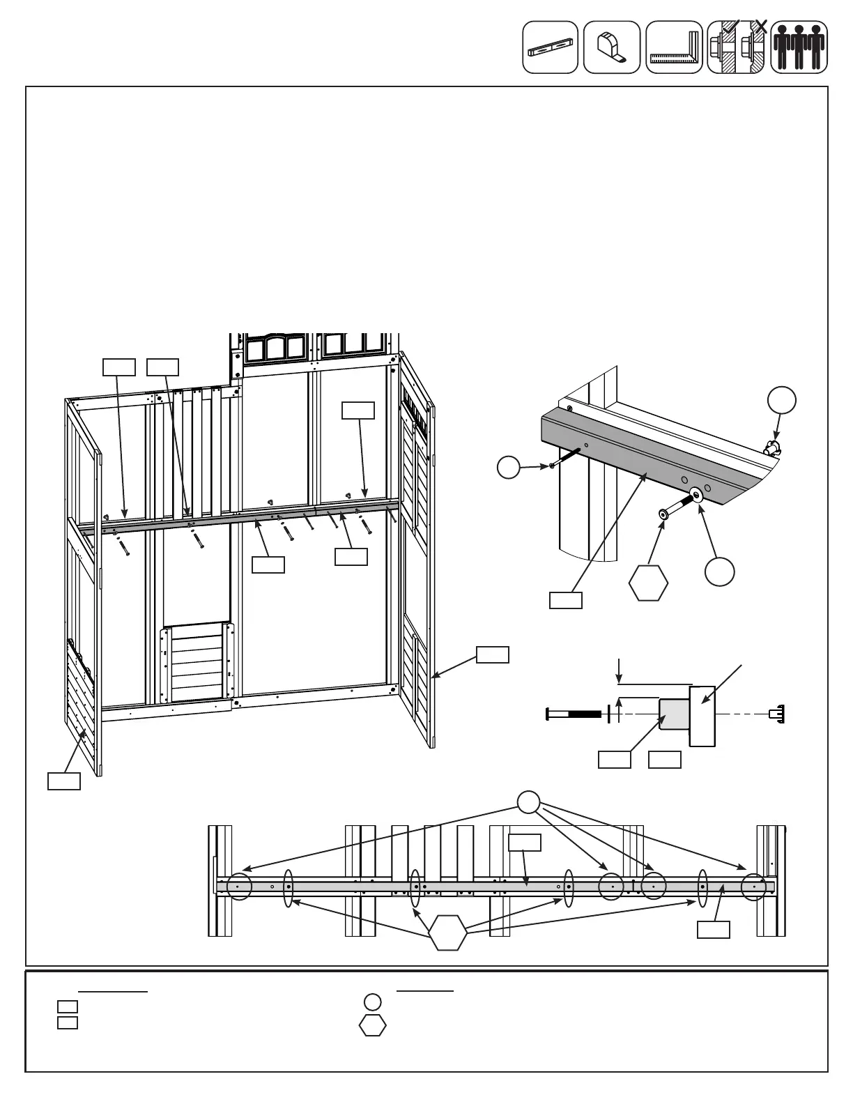
C: From inside the assembly, tight to the Front Wall Panel, measure 5/8” (16mm) down from the center of the
panel assembly and loosely attach 1 (9356) Side Floor Joist to Front Wall Panel using 3 (WB10) 5/16 x 2-5/8”
Wafer Bolts (with at washer and t-nut), making sure that it’s tight to the (9214) End Slide Panel. Bolts are
installed from inside the assembly. (g 7.2, 7.3, 7.4 and 7.5)
D: Place (9382) Side Joist so that it ts between the (9356) Side Floor Joist and (9213) SW Wall Panel and
loosely attach using 1 (WB10) 5/16 x 2-5/8” Wafer Bolt (with at washer and t-nut). (g 7.2, 7.3, 7.4 and 7.5)
E: Make sure (9356) Side Floor Joist and (9382) Side Joist are level then attach with 2 (S3) #8 x 2-1/2” Wood
Screws per joist and tighten bolts. (g 7.2, 7.3 and 7.5)
F: Repeat Steps B - D to install (9356) Side Floor Joist and (9382) Side Joist to the Back Wall Panel.
9213
9214
Step 7: Join Swing and Slide Assemblies
Part 2
TN2
FW2