73
Hardware
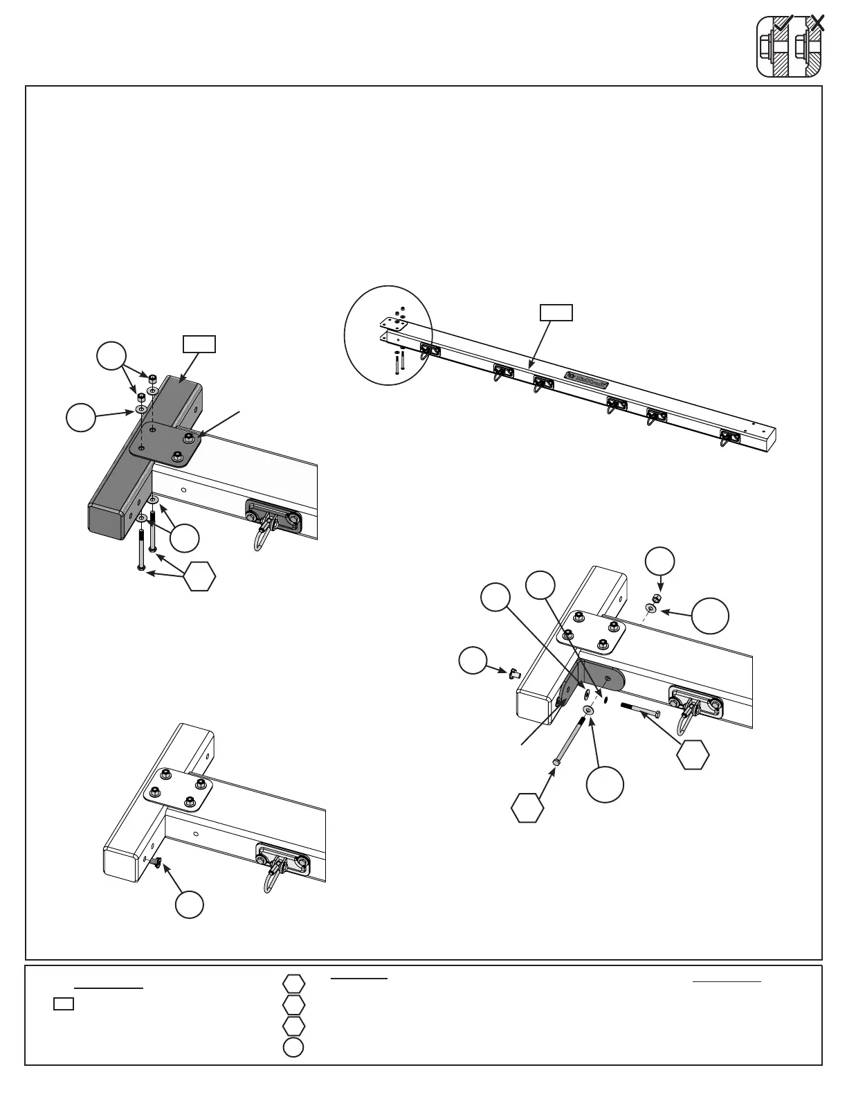
D: On the Fort End of (9452) Engineered SW Beam attach 2 Heavy Flat Brackets with 2 (G21) 5/16 x 3-3/4”
Hex Bolts (with 2 at washers and 1 lock nut). (g. 29.4 & 29.5)
E: Place (9352) SW Mount in between both Heavy Flat Brackets. Attach (9352) SW Mount to Heavy Flat
Brackets with 2 (G21) 5/16 x 3-3/4” Hex Bolts (with 2 at washers and 1 lock nut) (g 29.4). Install a 5/16” t-nut
into the bottom pre-drilled hole in the (9352) SW Mount as shown in g. 29.6.
F: Place 1 Heavy L-Bracket against (9452) Engineered SW Beam and (9352) SW Mount. Attach with 1 (G17)
3/8 x 6” Hex Bolt (with 2 at washers and lock nut) and 1 (G10) 5/16 x 3” Hex Bolt (with lock washer, at
washer and t-nut). (g 29.7)
4 x 5/16 x 3-3/4” Hex Bolt (FW2 x 2, LN2)
1 x 3/8 x 6” Hex Bolt (FW10 x 2 & LN3)
1 x 5/16 x 3” Hex Bolt (LW2, FW2, TN2)
1 x
Other Parts
2 x Heavy Flat Bracket
1 x Heavy L-Bracket
G21
G17
G10
Wood Parts
1 x SW Mount 3 x 3 x 16”
9352
Fort End
Fig. 29.5
Fig. 29.7
G17
Heavy Flat
Bracket
Fig. 29.4
9352
G10
Heavy
L-Bracket
9452
Fig. 29.6
Step 29: Swing Beam Assembly
Part 2
Note: It is important to note
hole orientation for this step.
G21
FW2
FW2
TN2
TN2
FW2
LW2
LN3
FW10
FW10
TN2
LN2