Issue: 08/2012
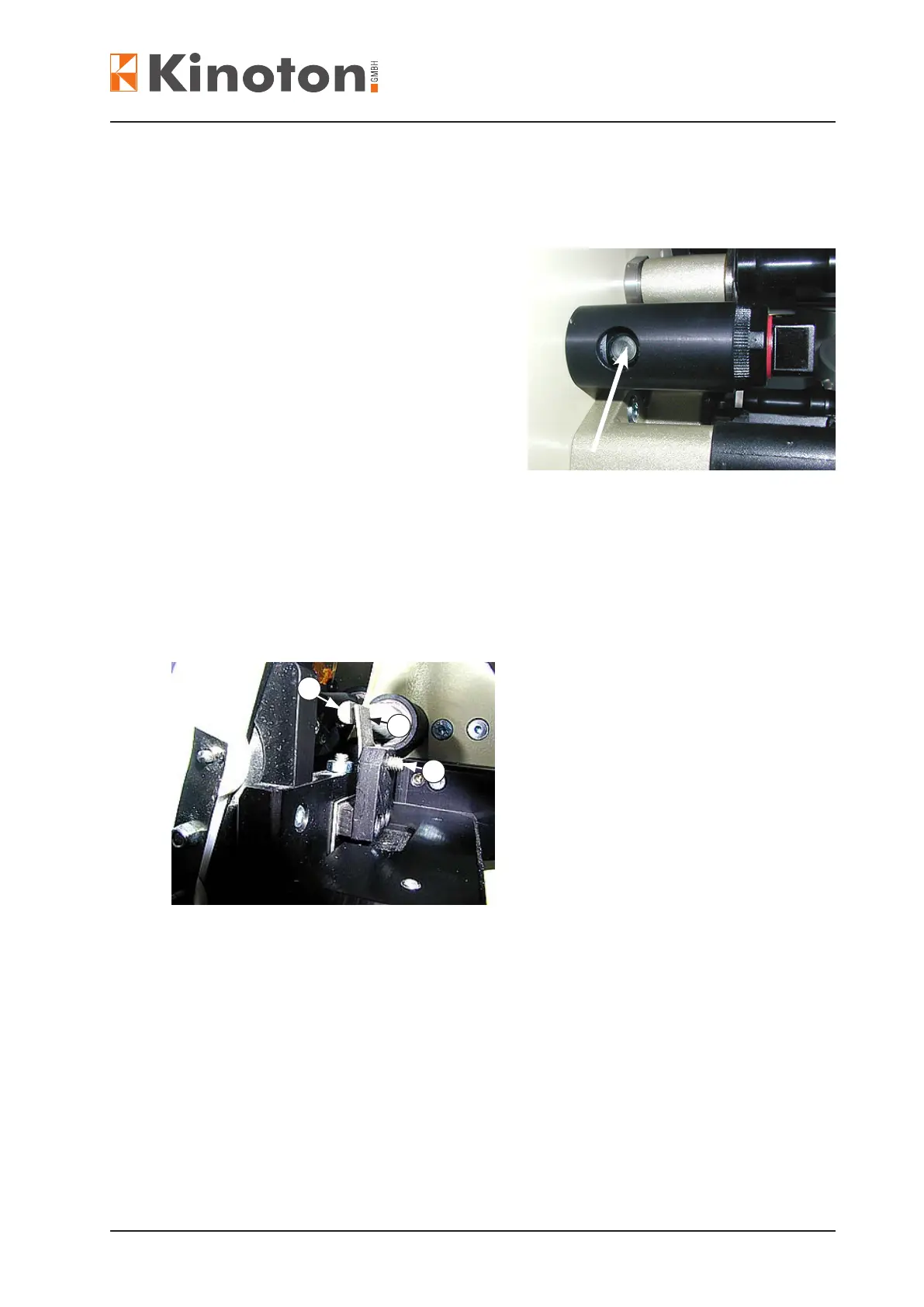
Position the sensor (arrow) in a way that it “looks” vertically towards the lm surface.
The sensor’s view must be perpendicular to the lm.
• To adjust the sensitivity of the sensor
thread a lm and turn the plastic screw
(arrow) with a screw driver until the red
LED (adjusting aid) blinks.
• Then turn the screw until the LED surely
lights steadily.
• Switch on the projector.
$As soon as the boot phase is nished, the skate lifting will be activated. From this
moment on the correct function can be checked or adjustments can be carried out.
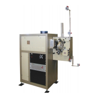
1
2
3
$The skate lifting device essentially consists of a rotation shaft with a at side which
is driven by a solenoid.
$When active the round side of the shaft presses against a metal plate Á and releases
the pressure from the lm (the skate is lifted).
$When not active the at side of the shaft points towards the metal plate, but does not
touch it - pressure is exerted on lm.
$When the skate is lifted (reverse running or pausing) the gap between the skate and
the runners should range between 0.5 and 1 mm in the area of the upper ceramics
roller.
• The skate lifting can be adjusted by turning the grub screw  (Allen key 2).
The contact areas of the shaft and the plate should be slightly greased.
Repair and Adjustments