Issue: 08/2012
$The more the skate and the runners wear the more the pressure has to be
increased for best picture steadiness.
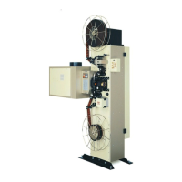
$With the time the indicator  will move
more and more to the left, in the direction
of the lm gate.
$As soon as the indicator reaches the out-
most left position a general re-adjustment
is necessary.
• For this, turn the ne adjusting screw
anticlockwise until the indicator position
reaches the outmost right side.
• Now loosen the lock nut Ã, (wrench size
13 mm or knurled nut), and adjust the skate pressure by turning the adjusting screw
Á until the picture on the screen is just at the edge to become unsteady.
• Fix the adjustment by tightening the lock nut Ã.
• Then turn the upper ne adjusting screw until the picture just becomes steady.
$These adjustments are correct when the indicator  is now positioned in the right
third of the scale and the picture on the screen has just gone over the threshold from
unsteady to steady.
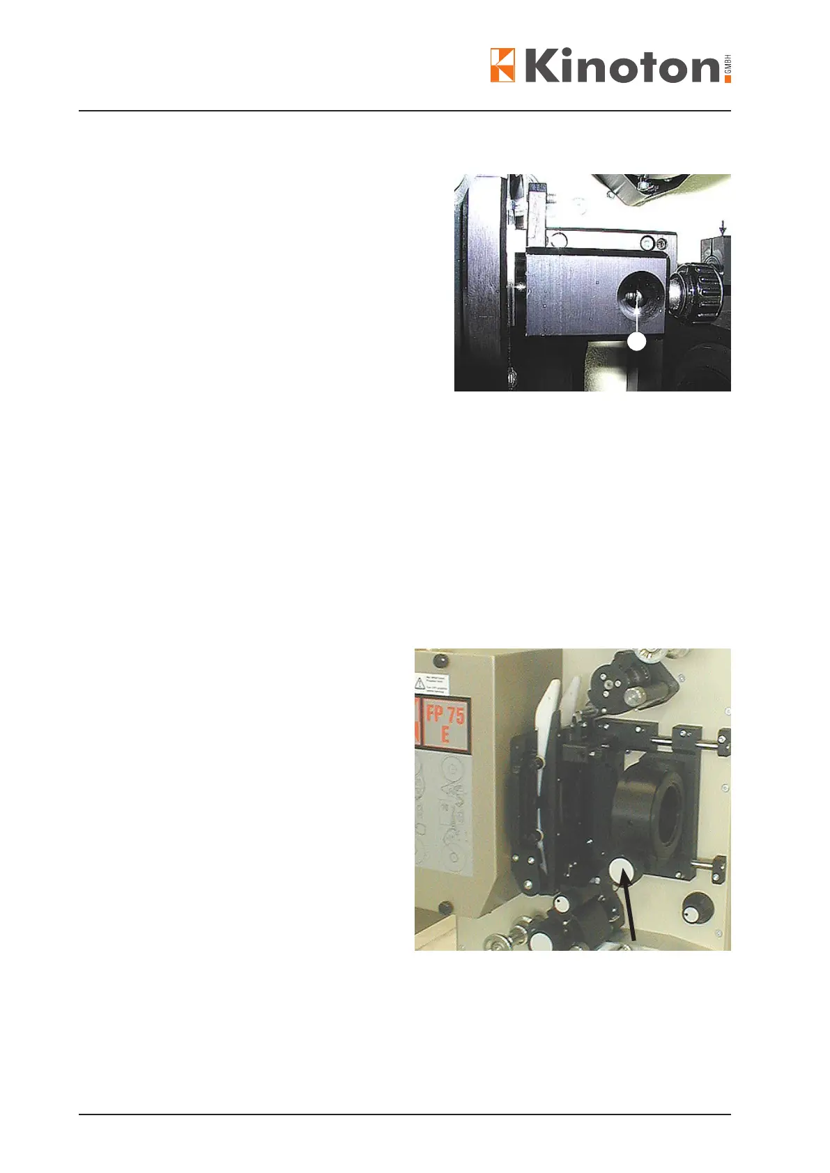
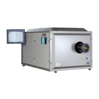
• Thread a test lm.
• Set the lens holder via the focusing
adjustment in the mid-position (mark-
ing position).
• Insert the lens and move it forwards
and backwards until the picture is
sharp. Mark this position in the lens
tube.
• Stop the projector.
• Loosen the handwheel (arrow) and
move the lens together with its tube
in the holder towards the lm gate.
$The lens clamping screw on tube will
be visible.
$Check the lens position in the tube
and if necessary correct the position
corresponding to your marking.
• Fix the lens in the tube by tightening the clamping screw (Allen key 3).
• Move the tube back to the stop.
• Fasten the handwheel (arrow).
3