9
Introduction
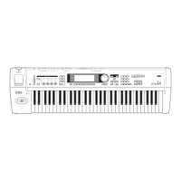
Rear panel
Rear panel
1. [POWER] switch
This switch turns the power on/off (☞p.17).
2. AC power supply connector (~AC9V)
Connect this to the included AC/AC power sup-
ply.
After connecting the power supply cable to this
instrument, connect the other end to an AC outlet
(
☞p.12).
3. AUDIO OUTPUT
Connect these outputs to the input jacks of your
amp or mixer. In addition to the L/MONO and R
main stereo audio outputs, this instrument pro-
vides two individual audio outputs. The sound
from each oscillator, drum, timbre/track, or inser-
tion effect can be freely routed to any output
(
☞p.97–).
(MAIN) L/MONO, R
These are unbalanced phone jacks (☞p.107).
These are the main audio output jacks. By setting
“Bus Select” to L/R, the output from an oscillator,
an insertion effect, an individual drum part, or the
metronome can be output to the (MAIN) L/
MONO and R jacks. When making connections in
stereo, use L/MONO and R. When making con-
nections in mono, use the L/MONO jack.
(INDIVIDUAL) 1, 2
These are unbalanced phone jacks (☞p.107).
These are individual (independent) audio output
jacks. These are individual (independent) audio
output jacks. By several times to make the “Bus
Select” to 1, 2, 1/2 an oscillator, an insertion effect,
an individual drum part, or the metronome etc.
can be assigned to be output from the (INDIVID-
UAL) 1, 2 jacks. The output from the 1, 2 jacks is
not affected by the [VOLUME] slider.
4. Pedal connections
ASSIGNABLE SWITCH jack
A separately sold on/off foot switch such as the
Korg PS-1 foot switch can be connected here
(
☞p.13).
Its function can be assigned in Global mode, allow-
ing you to use the foot switch as a modulation con-
troller, to select programs or combinations, or to
start/stop the sequencer (
☞p.101).
ASSIGNABLE PEDAL jack
A separately sold Korg EXP-2 or XVP-10 expres-
sion pedal can be connected here (
☞p.13).
Its function can be assigned in Global mode, allow-
ing you to use the pedal to control the volume, etc.
(
☞p.101)
DAMPER jack
A separately sold switch-type pedal such as the
Korg DS-1H damper pedal can be connected here.
If a DS-1H is connected, it will function as a half-
damper pedal. If another switch-type pedal is con-
nected, it will function as a damper switch. In
order to ensure that the half-damper pedal func-
tions correctly, please adjust the polarity and the
sensitivity (PG
☞p.135, 145).
5. MIDI
MIDI IN connector
Musical data and sound settings etc. are received
at this connector.
Use this to play this instrument from another con-
nected MIDI device (
☞PG p.245).
MIDI OUT connector
Musical data and sound settings etc. are transmit-
ted from this connector.
Use this to control another connected MIDI device
from this instrument (
☞PG p.245).
MIDI THRU connector
Musical data and sound settings etc. that are
received at the MIDI IN connector are re-transmit-
ted without change from the MIDI THRU connec-
tor.
You can use this to connect multiple MIDI devices
via MIDI cables (
☞PG p.245).
1
23
4
5
 Loading...