2JN
2-2-1
2-2 Electrical Parts Layout
2-2-1 Electrical parts layout
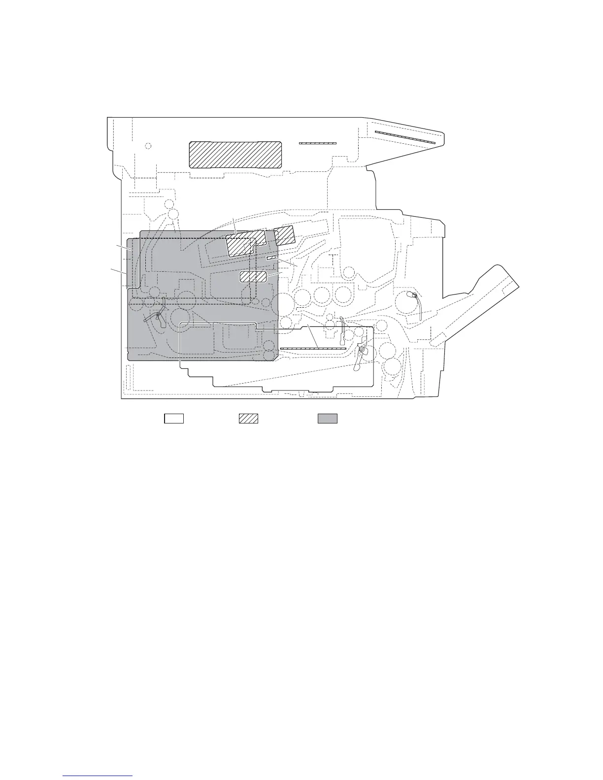
(1) PWBs
Figure 2-2-1 PWBs
1. Control PWB ................................................ Main controller: Controls the software such as the print data processing
and provides the interface with computers.
Engine: Controls machine hardware such as high voltage/bias output
control, paper conveying system control, and fuser temperature control,
etc.
2. Power source PWB...................................... After full-wave rectification of AC power source input, switching for
converting to 24 V DC for output. Controls the fuser heater lamp.
3. High voltage PWB........................................ Generates main charging, developing bias and transfer bias.
4. Operation panel PWB .................................. Consists the LCD, LED indicators and key switches.
5. APC PWB .................................................... Generates and controls the laser beam.
6. PD PWB....................................................... Controls horizontal synchronizing timing of laser beam.
7. Zener PWB .................................................. Adjusts the drum surface potential.
8. Eraser lamp PWB ........................................ Eliminates the residual electrostatic charge on the drum.
9. Scanner PWB .............................................. Controls the scanner section.
10. CCD PWB .................................................... Reads the image of originals.
11. Inverter PWB................................................ Controls the exposure lamp.
12. FAX PWB ..................................................... Modulates, demodulates, compresses, decompresses and smoothes out
image data, and converts resolution of image data.
Machine insideMachine left Machine right
1
2
4
5
7
8
6
9
10 11
12
3
 Loading...