119
14 Appendix
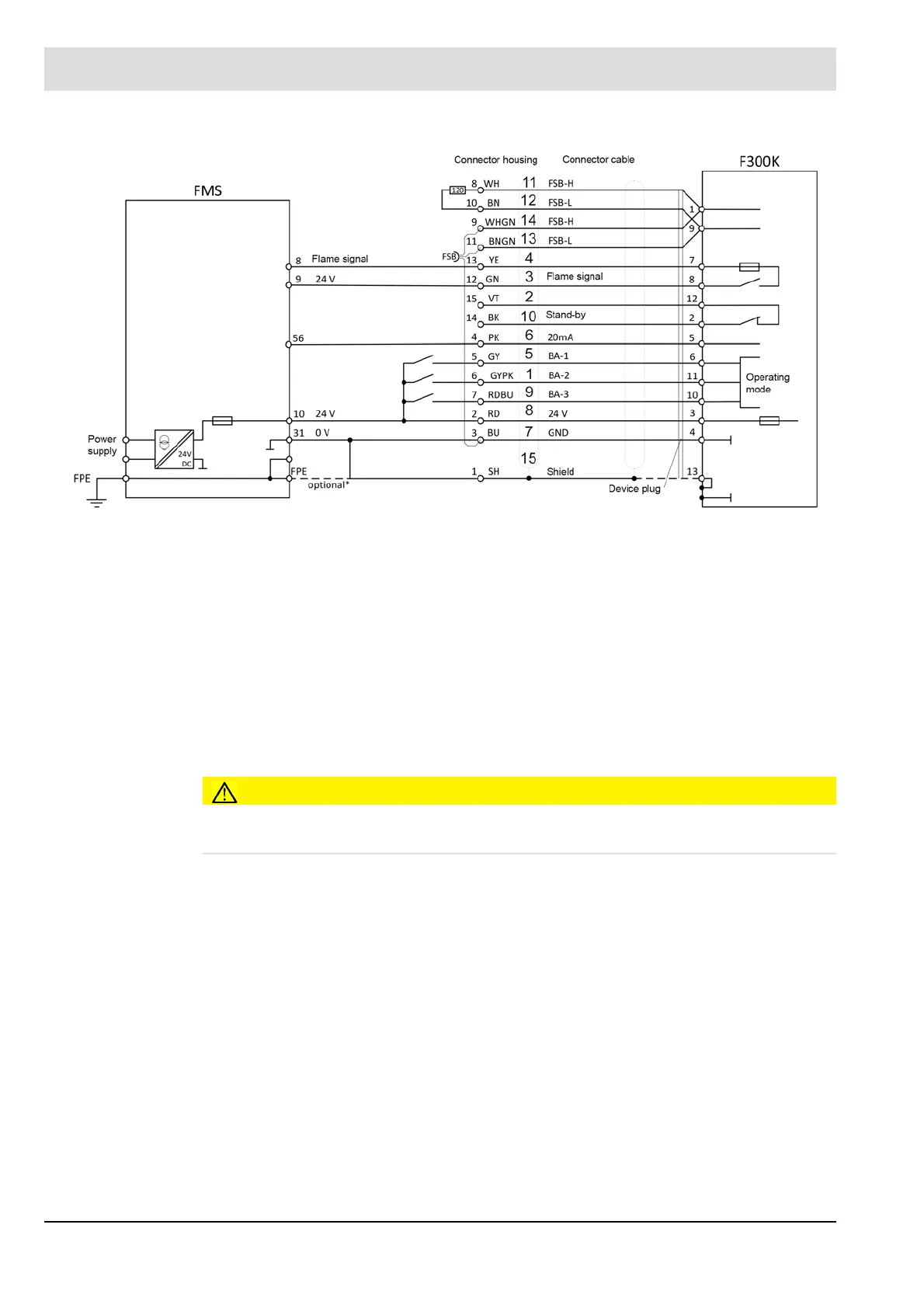
Fig. 14-31 F300K - FMS connection diagram
* Optional for the derivation of exceptional EMC interference. The link leads to a short circuit between chassis groun-
dand FPE. As a result, it may come to influence devices with the same ground reference.
CAUTION!
If the F300KUI or F300K +FB30 is connected, no other device may be connected to the Eta-
matic 24V supply.
BN = brown BK = black BU = blue
GN = green GY = grey PK = pink
RD = red VT = violet WH = white
YE = yellow SH = shield WHGN = white-green
GYPK = grey-pink RDBU = red-blue BNGN = brown-green

 Loading...