76
7 Operation
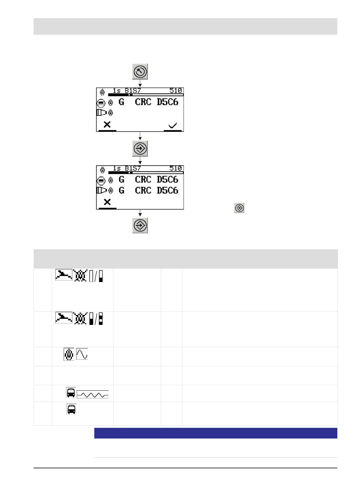
Sending changed parameter data to the flame scanner
You will find more information on the values in the following table:
NOTICE
Should there be more than 2 devices connected to the BUS (e.g. F300K, FB30), only the last
two devices which are connected to the BUS are allowed to have a BUS terminating resistor.
Press within 8 seconds.
Icon Name Valu
e
Explanation
55: Intensity 1 –
display
0/1 Category of the flame register’s output when the flame is
OFF for current output and LED chain.
0 = current output and LED chain, always 0 % (default)
1 = current output and LED chain indicate the current
status of the flame signal
56: Intensity 2 –
LED resolution
0/1 Intensity signal of the LED chain for the flame signal
(only for the F300K without an integrated UI)
0 = low resolution 100 % of LED = default
1 = high resolution 100 % of LED
57:
mA
Current loop 1,
signal type
0/1 0 = display of the flame intensity = default
1 = display of effective value
54: mA 0/4 Current loop 2,
range
0/4 0 = 0 ... 20 mA (default)
4 = 4 ... 20 mA
59:
2
Bus
termination
0/1 OFF, ON (bus terminating resistor)
1 = default
64:
2 ID
Consec. no. on
bus
1 -
32
Differentiation of different flame scanners on the same
bus
1 = default
 Loading...