ECO GOLD
25/08/2011/ YACE0088 Appendix with settings 105
Connection of analogue inputs and outputs
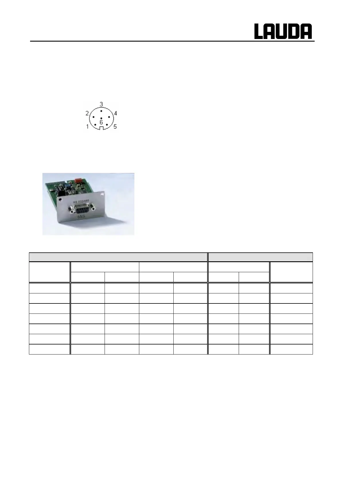
A six-pole round connector with screw lock and contact assignment according to DIN EN 60130-9 or
IEC 130-9 are required.
A suitable coupling plug is obtainable under the catalogue no. EQS 057.
View of socket (front) or solder side of plug:
Socket 74S
Contact 1 Output 1
Contact 2 Output 2
Contact 3 0 V reference potential
Contact 4 Input 1
Contact 5 +20 V (max. 0.1 A)
Contact 6 Input 2
Note: Only use screened connecting leads and connect the screen to the plug housing.
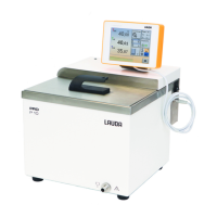
G.3 RS 232/485 interface module
RS 232/485 Interface Module
(LAUDA catalogue no. LRZ 913) with nine-pole SUB-D socket.
Electrically isolated using optocouplers. With the LAUDA instruc-
tion set, extensively compatible to Ecoline, Proline and Integral
series.
The RS 232 interface can be connected directly to the PC with a
1:1 connected cable (catalogue no. EKS 037, 2 m cable and EKS
057, 5 m cable).
G.3.1 Connecting lead and interface test RS 232
Computer Thermostat
Signal 9-pole Sub-D socket 25-pole Sub-D socket 9-pole Sub-D socket Signal
{ | { | { |
R x D 2 2 3 3 2 2 T x D
T x D 3 3 2 2 3 3 R x D
DTR 4 20 4 DSR
Signal Ground 5 5 7 7 5 5 Signal Ground
DSR 6 6 6 DTR
RTS 7 4 7 CTS
CTS 8 5 8 RTS
{ with hardware handshake: On connecting a thermostat to the PC use a 1:1 and not a null-modem ca-
ble.
| without hardware handshake: Set the operating mode on the PC "without hardware handshake".
− Use screened leads and connect screen to plug case.
− The wires are electrically isolated from the rest of the electronics.
− Non-assigned pins should not be connected.
The RS 232 interface can be checked in a simple way with a connected PC running Microsoft Windows
operating system. With Windows
®
95/98/NT/XP using the program "Hyper Terminal".