The Interlock System, consisting of: blade con-
trol bail which operates the flywheel brake and
switch assembly or blade brake clutch (BBC)
interlock switch, chute interlock switch, BBC
throttle stop switch and connecting wiring har-
ness. These switches control when the engine
can
be
started,
is
automatically stopped or con-
tinues to run depending on the action of each
switch in the complete circuit. They all are
connected to the CD Ignition Module to ground
out the ignition and stop the engine or prevent
the engine from being
started
in an unsafe
operating condition.
SAFETY WARNING: When testing a
mower never disconnect all interlock
switches at one time
so
you
have no way to
stop the engine. After performing Interlock
system tests make sure ail switches have
been reconnected and test for proper
operation or injury from blade or thrown
ob]ect could occur.
Refer to Wiring Diagrams for connector identi-
fication called out in the following procedures at
end of Section
5.
i-*
A
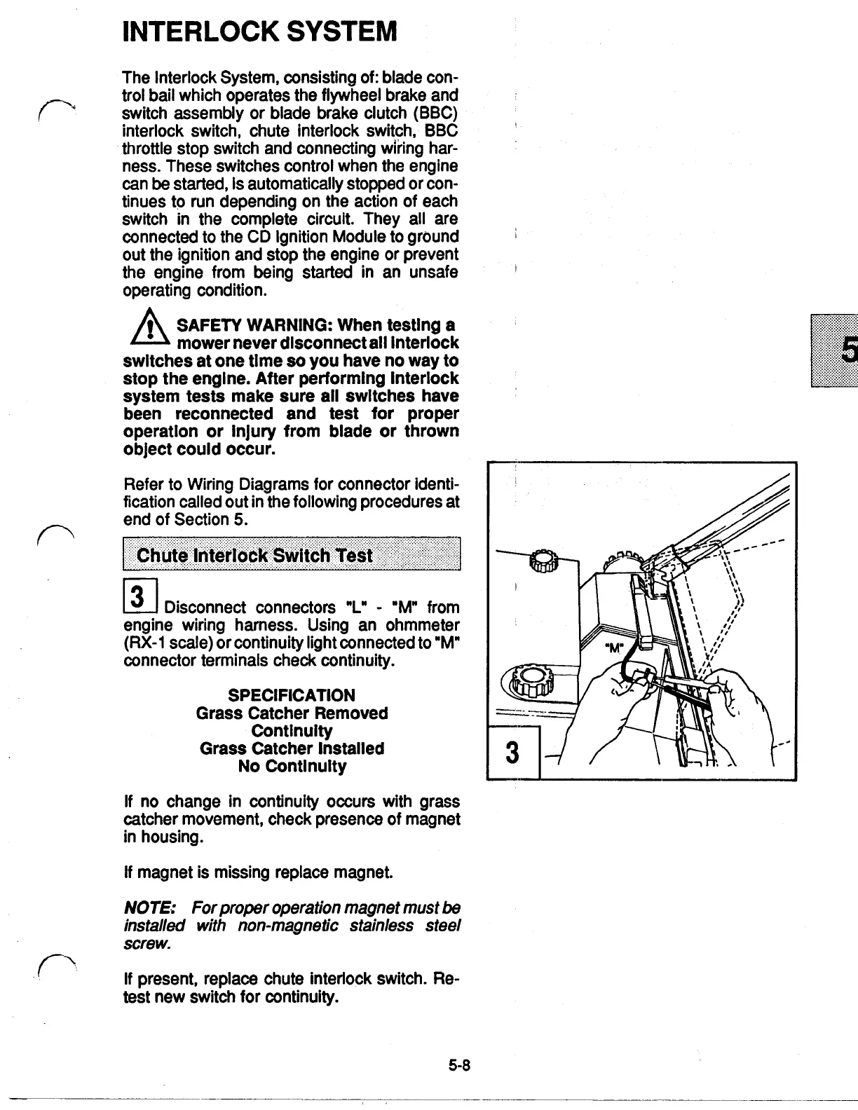
Disconnect connectors
"L"
"M" from
engine wiring harness. Using an ohmmeter
(RX-1
scale) or continuity light connected to "M"
connector terminals check continuity.
SPECIFICATION
Grass Catcher Removed
Continuity
Grass Catcher Installed
No Continuity
If
no change in continuity occurs with grass
catcher movement, check presence of magnet
in
housing.
If
magnet is missing replace magnet.
NOTE:
For proper operation magnet must
be
installed with non-magnetic stainless steel
screw.
If
present, replace chute interlock switch. Re-
test new switch
for
continuity.
5-8
 Loading...