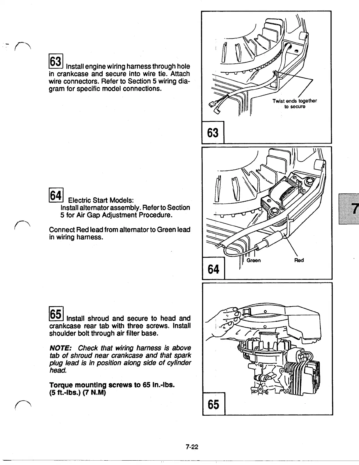
63
Install engine wiring harness through hole
in crankcase and secure into wire tie. Attach
wire connectors. Refer to Section
5
wiring dia-
gram for specific model connections.
64
Electric Start Models:
Install alternator assembly. Refer to Section
5
for Air
Gap
Adjustment Procedure.
Connect Red lead from alternator to Green lead
in wiring harness.
Install shroud and secure to head and
crankcase rear tab
with
three screws. Install
shoulder bolt through air filter base.
NOTE:
Check that wiring harness is above
tab
of
shroud near crankcase and that spark
plug
lead is in position along side
of
cylinder
head.
Torque mountlng
screws
to
65
in.-lbs.
(5
ft.-lbs.)
(7
N.M)
7-22
 Loading...