EasyManuals Logo

LeCroy WaveAce series User Manual

Default Icon
106 pages
To Next Page IconTo Next Page
To Previous Page IconTo Previous Page
Page #17 background imageLoading...
Page #17 background image
WaveAce Series
17
WA-GSM-E RevB
3. Menu On/Off, Menu Option buttons and Print button
4. Front Panel Controls
5. Channel inputs, External Trigger input, Probe connect
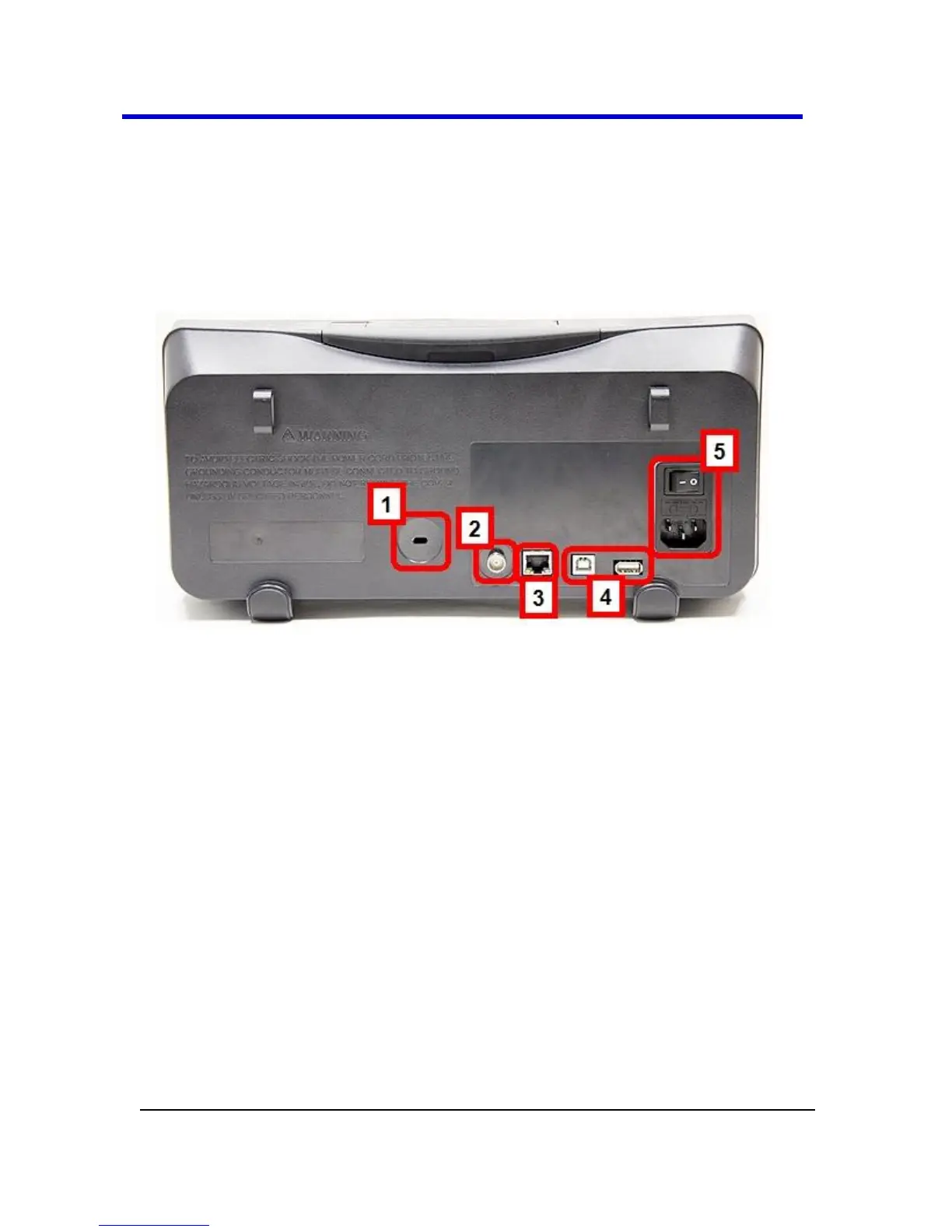
Back and Side Connections
The following images show back and side panel connection locations on
both 4 and 2 channel models.
Figure 4-3. Back panel connection locations on the 4 Channel WaveAce
Oscilloscope.
Previously numbered front panel buttons and knob locations for the 4
channel model correspond with the following explanations.
1. Security Lock Receptacle
2. Pass/Fail Output
3. RJ-45 Connector
4. USB Type B and A Receptacles
5. Power Shutoff Switch and Input Connector

Table of Contents

Questions and Answers:

Question and Answer IconNeed help?

Do you have a question about the LeCroy WaveAce series and is the answer not in the manual?

LeCroy WaveAce series Specifications

General IconGeneral
Channels2 or 4
Vertical Resolution8-bit
Input CouplingAC, DC, GND
Power Supply100-240 VAC, 50/60 Hz
Sample Rate2 GS/s
Display800 x 480
Input Impedance1 MΩ
Timebase Range5 ns/div to 50 s/div
Trigger TypesEdge, Pulse Width, Video, Slope
ConnectivityUSB host, USB device

Related product manuals