Vertical Settings and Channel
Controls
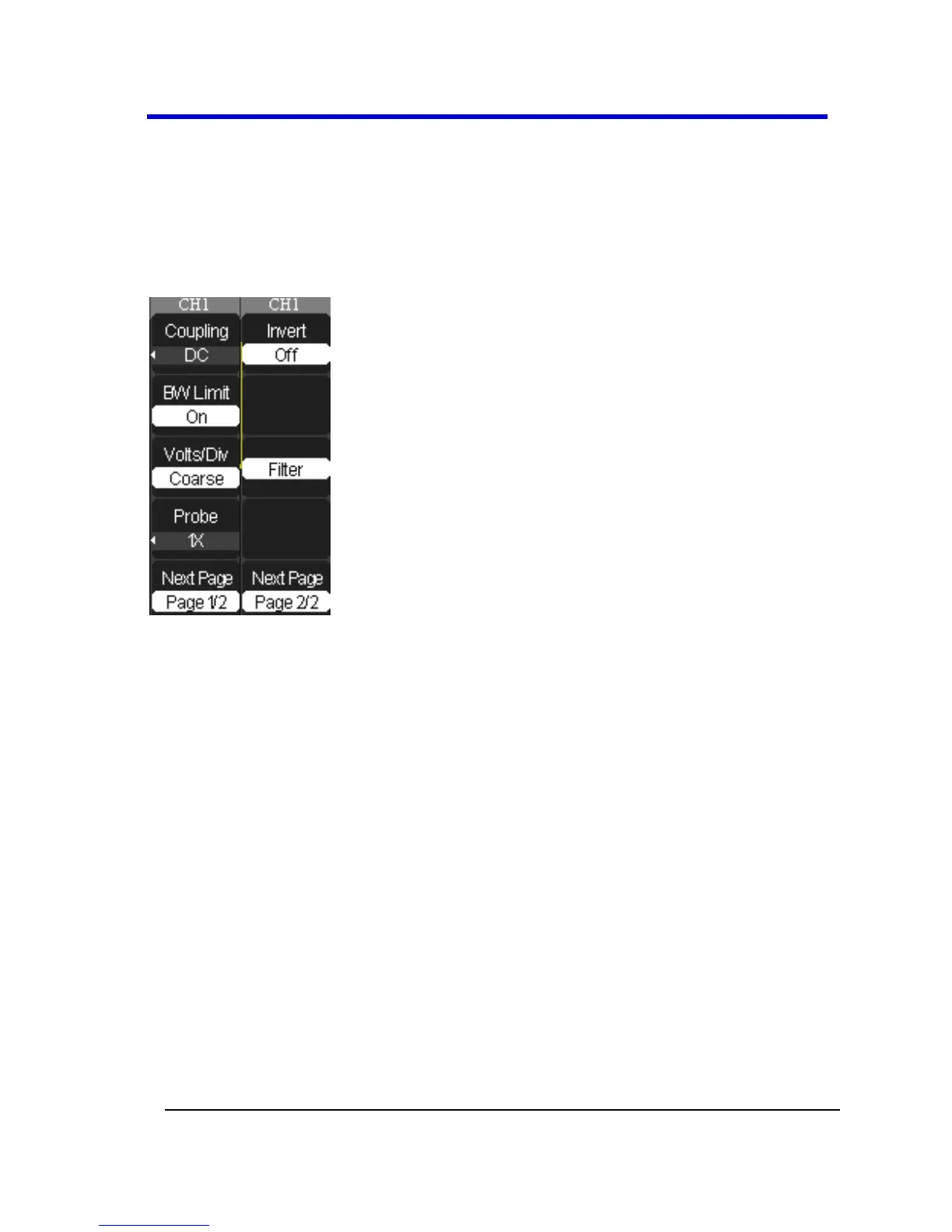
When you turn a channel trace ON, the Channel flyout menu opens. The
Channel menu page shown (1/2 or 2/2) is always based on the most recent
trace activated.
Choosing Coupling
You can choose one of these input coupling modes:
DC - Passes both AC and DC components of the input signal.
AC - Blocks the DC component of the input signal and attenuates
signals below 10 Hz.
GND - Disconnects the input signal. Use GND coupling to display a
zero-volt waveform. Internally, the channel input is connected to a
zero-volt reference level.
PLEASE NOTE THE FOLLOWING:
If the channel is set to DC coupling, you can quickly measure the DC
component of the signal by simply noting its distance from the
ground symbol.
If the channel is set to AC coupling, the DC component of the signal
is blocked allowing you to use greater sensitivity to display the AC
component of the symbol.