X-Stream Operator’s Manual
WM-OM-E Rev I 257
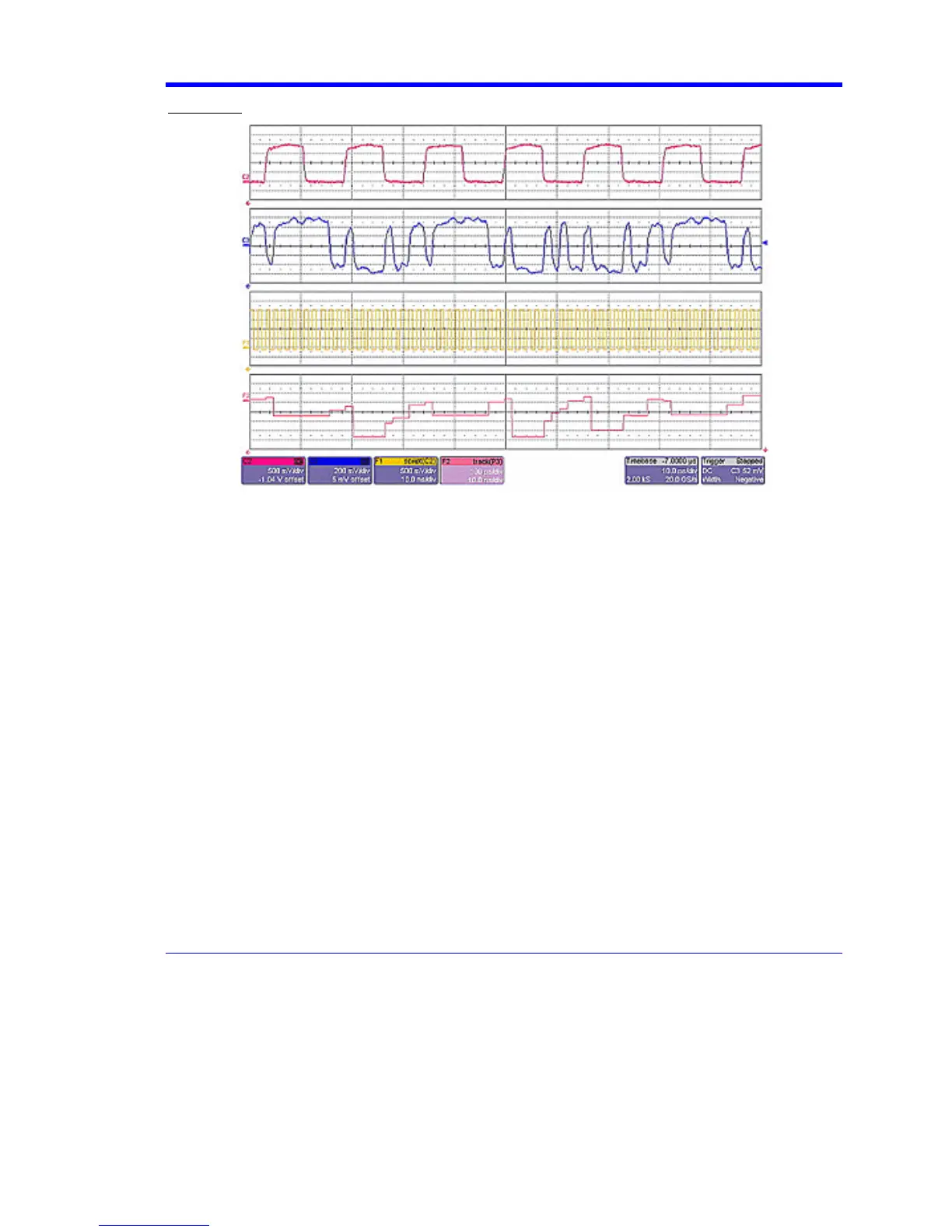
Example 4
Example 4 is a measurement of DVI (Digital Video Interface) Data-Clock skew jitter measurement,
using a VBScript to emulate the PLL.
In this example, a customer was not able to probe the desired clock signal. The only probing point
available was the output differential clock signal (C2). However, that clock was a factor of 10 slower
than the clock embedded in the data signal (C3). By using a VBScript to create a clock waveform of
the appropriate frequency (waveform F1), the customer was able to display and measure
data-clock skew using a LeCroy instrument function and parameter.