The following are important messages or warnings that may appear.
Messages Description
V not suitable\r\nfor Calib-
ration
The vertical angle deviates from the required
horizontal / line-of-sight. Aim correctly at
the target point. Conrmation of the mes-
sage required.
Compensator
unstable.\r\nPlease
remeasure.
Computed values out of tolerance. The previ-
ous values are retained and measurements
should be repeated. Conrmation of the
message required.
Compensator
unstable.\r\nPlease
remeasure.
Measurement error appears when, for
example, there is an unstable set up. Repeat
the process. Conrmation of the message
required.
11.1.4 Adjusting the Compensator
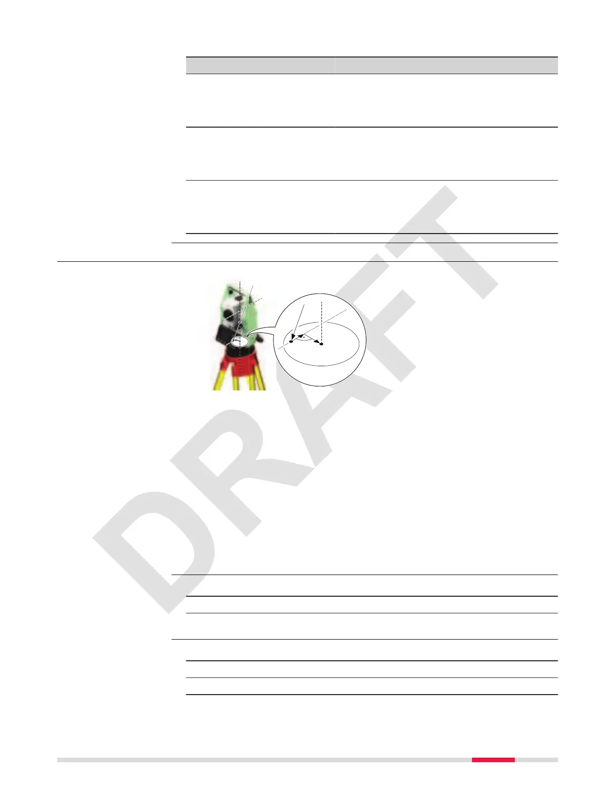
a Mechanical vertical axis of the
instrument, also called stand-
ing axis
b Plumb line
c Longitudinal component (l) of
the compensator index error
d Transversal component (t) of
the compensator index error
The compensator index errors (l, t) occur, if the vertical axis of the instrument
and the plumb line are parallel but the zero points of the compensator and the
level do not coincide. The calibration procedure electronically adjusts the zero
point of the compensator.
A longitudinal component in direction of the telescope and a transversal com-
ponent perpendicular to the telescope dene the plane of the dual axis com-
pensator of the instrument.
The longitudinal compensator index error (l) has a similar effect as the vertical
index error and effects all vertical angle readings.
The transversal compensator index error (t) is similar to the tilting axis error.
The effect of this error to the horizontal angle readings is 0 at the horizon
and increases with steep sightings.
1. Select Tools in the Main Menu.
2. Select Check & Adjust in the Tools menu.
3. Select Compensator in the Calibration menu.
1. Level the instrumentl.
2. Press OK to measure the rst face. No target has to be aimed at.
3. OK to release the measurement in the other face.
Messages
Compensator index
error
Access
Check and adjust
step-by-step
Tools 87


 To Next Page